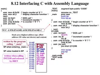
More IP
More IP. Fragmentation, NAT, IPv6, MPLS. Readings. IP format, fragmentation - 4.1.2 ICMP - 4.1.7 NAT - side bar, pp. 327-329 IPv6 - 4.3.5 MPLS - 4.5. IP Packet Format. 0. 4. 8. 16. 19. 31. TOS. Length. Version. HLen. Ident. Flags. Offset. TTL. Protocol. Checksum.

More IP
E N D
Presentation Transcript
More IP Fragmentation, NAT, IPv6, MPLS
Readings • IP format, fragmentation - 4.1.2 • ICMP - 4.1.7 • NAT - side bar, pp. 327-329 • IPv6 - 4.3.5 • MPLS - 4.5
IP Packet Format 0 4 8 16 19 31 TOS Length Version HLen Ident Flags Offset TTL Protocol Checksum SourceAddr DestinationAddr Pad Options (variable) (variable) Data
IP Packet Format • 4-bit version • IPv4 = 4, IPv6 = 6 • 4-bit header length • Counted in words, minimum of 5 • 8-bit type of service field (TOS) • Mostly unused • 16-bit data length • Counted in bytes
IP Packet Format • Fragmentation support • 16-bit packet ID • All fragments from the same packet have the same ID • 3-bit flags • 1-bit to mark last fragment • 13-bit fragment offset into packet • Counted in 8-byte words • 8-bit time-to-live field (TTL) • Hop count decremented at each router • Packet is discard if TTL = 0
IP Packet Format • 8-bit protocol field • TCP = 6, UDP = 17 • 16-bit IP checksum on header • 32-bit source IP address • 32-bit destination IP address • Options • Variable size • Source-based routing • Record route • Padding • Fill to 32-bit boundaries
IP Packet Size • Problem • Different physical layers provide different limits on frame length • Maximum transmission unit (MTU) • Source host does not know minimum value • Especially along dynamic routes
MTUs • Ethernet - 1500 bytes • FDDI - 4500 bytes • 802.11 - 2304 bytes • PPP - 512 bytes
IP Fragmentation and Reassembly • Solution • When necessary, split IP packet into acceptably sized packets prior to sending over physical link • Questions • Where should reassembly occur? • What happens when a fragment is damaged/lost?
IP Fragmentation and Reassembly • Fragments are self-contained IP datagrams • Reassemble at destination to minimize refragmentation • Drop all fragments in packet if one or more fragments are lost • Avoid fragmentation at source host • Transport layer should send packets small enough to fit into one MTU of local physical network • Must consider IP header • Note: MTU in ATM is based on CS-PDU size
Start of header Ident = x 0 Offset 0 Rest of header H1 R1 R2 R3 H2 1400 data bytes ETH FDDI PPP ETH Start of header Ident = x 1 Offset 0 Rest of header 512 data bytes ETH ETH ETH PPP FDDI PPP PPP ETH IP IP IP IP IP IP IP IP (376) (512) (512) (512) (512) (1400) (1400) (376) Start of header Ident = x 1 Offset 512 Rest of header 512 data bytes Start of header Ident = x 0 Offset 1024 Rest of header 376 data bytes IP Fragmentation and Reassembly
FTP HTTP NV TFTP TCP UDP IP ICMP Ethernet FDDI ATM Modem Internet Control Message Protocol (ICMP) • IP companion protocol • Handles error and control messages
ICMP • Error Messages • Host unreachable • Reassembly failed • IP checksum failed • TTL exceeded (packet dropped) • Invalid header • Control Messages • Echo/ping request and reply • Echo/ping request and reply with timestamps • Route redirect
Source sends series of UDP segments to dest First has TTL =1 Second has TTL=2, etc. Unlikely port number When nth datagram arrives to nth router: Router discards datagram And sends to source an ICMP message (type 11, code 0) Message includes name of router& IP address When ICMP message arrives, source calculates RTT Traceroute does this 3 times Stopping criterion UDP segment eventually arrives at destination host Destination returns ICMP “host unreachable” packet (type 3, code 3) When source gets this ICMP, stops. Traceroute and ICMP
NAT: Network Address Translation rest of Internet local network (e.g., home network) 10.0.0/24 10.0.0.1 10.0.0.4 10.0.0.2 138.76.29.7 10.0.0.3 All datagrams leaving local network have same single source NAT IP address: 138.76.29.7, different source port numbers Datagrams with source or destination in this network have 10.0.0/24 address for source, destination (as usual)
NAT: Network Address Translation • Motivation: local network uses just one IP address as far as outside world is concerned: • range of addresses not needed from ISP: just one IP address for all devices • can change addresses of devices in local network without notifying outside world • can change ISP without changing addresses of devices in local network • devices inside local net not explicitly addressable, visible by outside world (a security plus).
NAT: Network Address Translation Implementation: NAT router must: • outgoing datagrams:replace (source IP address, port #) of every outgoing datagram to (NAT IP address, new port #) . . . remote clients/servers will respond using (NAT IP address, new port #) as destination addr. • remember (in NAT translation table) every (source IP address, port #) to (NAT IP address, new port #) translation pair • incoming datagrams:replace (NAT IP address, new port #) in dest fields of every incoming datagram with corresponding (source IP address, port #) stored in NAT table
3 1 2 4 S: 10.0.0.1, 3345 D: 128.119.40.186, 80 S: 138.76.29.7, 5001 D: 128.119.40.186, 80 1: host 10.0.0.1 sends datagram to 128.119.40.186, 80 2: NAT router changes datagram source addr from 10.0.0.1, 3345 to 138.76.29.7, 5001, updates table S: 128.119.40.186, 80 D: 10.0.0.1, 3345 S: 128.119.40.186, 80 D: 138.76.29.7, 5001 NAT: Network Address Translation NAT translation table WAN side addr LAN side addr 138.76.29.7, 5001 10.0.0.1, 3345 …… …… 10.0.0.1 10.0.0.4 10.0.0.2 138.76.29.7 10.0.0.3 4: NAT router changes datagram dest addr from 138.76.29.7, 5001 to 10.0.0.1, 3345 3: Reply arrives dest. address: 138.76.29.7, 5001
NAT: Network Address Translation • 16-bit port-number field: • 60K simultaneous connections with a single LAN-side address! • NAT is controversial: • routers should only process up to layer 3 • violates end-to-end argument • NAT possibility must be taken into account by app designers, eg, P2P applications • address shortage should instead be solved by IPv6
IPv6 • History • Next generation IP (AKA IPng) • Intended to extend address space and routing limitations of IPv4 • Requires header change • Attempted to include everything new in one change • IETF moderated • Based on Simple Internet Protocol Plus (SIPP)
IPv6 • Wish list • 128-bit addresses • Multicast traffic • Mobility • Real-time traffic/quality of service guarantees • Authentication and security • Autoconfiguration for local IP addresses • End-to-end fragmentation • Protocol extensions • Smooth transition! • Note • Many of these functionalities have been retrofit into IPv4
3 m n o p 125-m-n-o-p 010 Region ID Provider ID Subscriber ID Subnet Host IPv6 Addresses • 128-bit • 3.4 x 1038 addresses (as compared to 4 x 10⁹) • Classless addressing/routing (similar to CIDR) • Address notation • String of eight 16-bit hex values separated by colons • 5CFA:0002:0000:0000:CF07:1234:5678:FFCD • Set of contiguous 0’s can be elided • 5CFA:0002::CF07:1234:5678:FFCD • Address assignment • Provider-based • geographic
0 8 16 31 version hdr len TOS length ident flags offset TTL protocol checksum source address destination address options (variable) pad (variable) IPv4 Packet Format • 20 Byte minimum • Mandatory fields are not always used • e.g. fragmentation • Options are an unordered list of (name, value) pairs
IPv6 Packet Format 0 8 16 31 version priority flow label payload length next header hop limit source address word 1 source address word 2 source address word 3 source address word 4 destination address word 1 destination address word 2 destination address word 3 destination address word 4 options (variable number, usually fixed length)
0 8 16 31 version priority flow label payload length next header hop limit source address 4 words destination address 4 words options (variable number, usually fixed length) IPv6 Packet Format • 40 Byte minimum • Mandatory fields (almost) always used • Strict order on options reduces processing time • No need to parse irrelevant options
IPv6 Packet Format • Version • 6 • Priority and Flow Label • Support service guarantees • Allow “fair” bandwidth allocation • Payload Length • Header not included • Next Header • Combines options and protocol • Linked list of options • Ends with higher-level protocol header (e.g. TCP) • Hop Limit • TTL renamed to match usage
IPv6 Extension Headers • Must appear in order • Hop-by-hop options • Miscellaneous information for routers • Routing • Full/partial route to follow • Fragmentation • IP fragmentation info • Authentication • Sender identification • Encrypted security payload • Information about contents • Destination options • Information for destination
0 8 16 31 next header length type value 0 8 16 31 next header 0 194 0 Payload length in bytes IPv6 Extension Headers • Hop-by-Hop extension • Length is in bytes beyond mandatory 8 • Jumbogram option (packet longer than 65,535 bytes) • Payload length in main header set to 0
IPv6 Extension Headers • Routing extension • Up to 24 “anycast” addresses target AS’s/providers • Next address tracks current target • Strict routing requires direct link • Loose routing allows intermediate nodes 0 8 16 31 next header 0 # of addresses next address strict/loose routing bitmap 1 – 24 addresses
IPv6 Extension Headers • Fragmentation extension • Similar to IPv4 fragmentation • 13-bit offset • Last fragment mark (M) • Larger fragment identification field 0 8 16 31 next header reserved offset reserved M ident
IPv6 Extension Headers • Authentication extension • Designed to be very flexible • Includes • Security parameters index (SPI) • Authentication data • Encryption Extension • Called encapsulating security payload (ESP) • Includes an SPI • All headers and data after ESP are encrypted
IPv6 Design Controversies • Address length • 8 byte • Might run out in a few decades • Less header overhead • 16 byte • More overhead • Good for foreseeable future • 20 byte • Even more overhead • Compatible with OSI • Variable length
IPv6 Design Controversies • Hop limit • 65,535 • 32 hop paths are common now • In a decade, we may see much longer paths • 255 • Objective is to limit lost packet lifetime • Good network design makes long paths unlikely • Source to backbone • Across backbone • Backbone to destination
IPv6 Design Controversies • Greater than 64KB data • Good for supercomputer/high bandwidth applications • Too much overhead to fragment large data packets • 64 KB data • More compatible with low-bandwidth lines • 1 MB packet ties up a 1.5MBps line for more than 5 seconds • Inconveniences interactive users
IPv6 Design Controversies • Keep checksum • Removing checksum from IP is analogous to removing brakes from a car • Light and faster • Unprepared for the unexpected • Remove checksum • Typically duplicated in data link and transport layers • Very expensive in IPv4
IPv6 Design Controversies • Mobile hosts • Direct or indirect connectivity • Reconnect directly using canonical address • Use home and foreign agents to forward traffic • Mobility introduces asymmetry • Base station signal is strong, heard by mobile units • Mobile unit signal is weak and susceptible to interference, may not be heard by base station
IPv6 Design Controversies • Security • Where? • Network layer • A standard service • Application layer • No viable standard • Application susceptible to errors in network implementation • Expensive to turn on and off • How? • Political import/export issues • Cryptographic strength issues
Transition From IPv4 To IPv6 • Not all routers can be upgraded simultaneous • no “flag days” • How will the network operate with mixed IPv4 and IPv6 routers? • Tunneling: IPv6 carried as payload in IPv4 datagram among IPv4 routers
A B E F F E B A tunnel Logical view: IPv6 IPv6 IPv6 IPv6 Physical view: IPv6 IPv6 IPv6 IPv6 IPv4 IPv4 Tunneling
Flow: X Src: A Dest: F data Flow: X Src: A Dest: F data Flow: X Src: A Dest: F data Flow: X Src: A Dest: F data D C F E B A F E B A Src:B Dest: E Src:B Dest: E Tunneling tunnel Logical view: IPv6 IPv6 IPv6 IPv6 Physical view: IPv6 IPv6 IPv6 IPv6 IPv4 IPv4 A-to-B: IPv6 E-to-F: IPv6 B-to-C: IPv6 inside IPv4 B-to-C: IPv6 inside IPv4
Multiprotocol label switching (MPLS) • initial goal: speed up IP forwarding by using fixed length label (instead of IP address) to do forwarding • borrowing ideas from Virtual Circuit (VC) approach • but IP datagram still keeps IP address! PPP or Ethernet header IP header remainder of link-layer frame MPLS header label Exp TTL S 5 1 3 20
MPLS capable routers • a.k.a. label-switched router • forwards packets to outgoing interface based only on label value (don’t inspect IP address) • MPLS forwarding table distinct from IP forwarding tables • signaling protocol needed to set up forwarding • RSVP-TE • forwarding possible along paths that IP alone would not allow (e.g., source-specific routing) !! • use MPLS for traffic engineering • must co-exist with IP-only routers
in out out label label dest interface 10 6 A 1 12 9 D 0 in out out label label dest interface in out out label label dest interface 8 6 A 0 6 - A 0 MPLS forwarding tables in out out label label dest interface 10 A 0 12 D 0 8 A 1 R6 0 0 D 1 1 R3 R4 R5 0 0 A R2 R1