Download
1 / 15
150 likes | 558 Vues
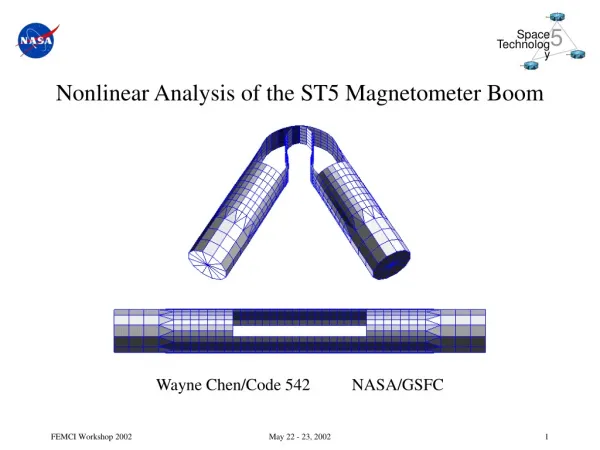
Nonlinear Analysis of the ST5 Magnetometer Boom Wayne Chen/Code 542 NASA/GSFC. Agenda. Problem Description Linear Versus Nonlinear Analysis Typical Model Trial and Error, Part 1 Trial and Error, Part 2 Trial and Error, Part 3 Refining the Design Latest Model Latest Results

E N D
Nonlinear Analysis of the ST5 Magnetometer Boom Wayne Chen/Code 542 NASA/GSFC May 22 - 23, 2002
Agenda • Problem Description • Linear Versus Nonlinear Analysis • Typical Model • Trial and Error, Part 1 • Trial and Error, Part 2 • Trial and Error, Part 3 • Refining the Design • Latest Model • Latest Results • Current Status • Conclusions / Lessons Learned May 22 - 23, 2002
Problem Description • Boom mounted magnetometer is one of the primary instruments on ST5 • Mission consists of a three S/C constellation to test nanosatellite technologies • Overall S/C dimensions ~ 18 in wide and ~ 10 in high • Overall S/C weight ~ 50 lb May 22 - 23, 2002
Problem Description (continued) • Because of postbuckling behavior, regular linear statics solution sequences not adequate May 22 - 23, 2002
Linear Versus Nonlinear Analysis • Linear analysis • Comprises bulk of the work done at GSFC • Useful for analysis of deployed boom (normal modes, thermal distortion, etc) • Nonlinear analysis • Minimal GSFC heritage, though capability has existed in various analysis codes • Only recently has nonlinear analysis been used for thin membranes, MEMS, and postbuckling • Analysis of the boom has been marked by steady progress through a lot of trial and error May 22 - 23, 2002
Typical Model • Main items of interest are torque capability of joint and tape stresses • Variables include material, radius of tapes, and size of windows Tube Tapes One [45] ply of 0.005” T300 May 22 - 23, 2002
Trial and Error, Part 1 • Early runs did not take into account contact between the tapes and used rigid elements (RBE2) at each end to enforce a rotation • Problem due to lack of contact between tapes is obvious • Behavior of end moment after snap-thru does not seem correct • Run time of 2.40 hrs May 22 - 23, 2002
Trial and Error, Part 2 • Contact between the tapes added and used rigid elements (RBE2) at each end to enforce a rotation • Contact between tapes more correctly modeled • Behavior of end moment after snap-thru still does not seem correct • Run time of 9.50 hrs May 22 - 23, 2002
Trial and Error, Part 3 • Contact between the tapes retained and rigid elements (RBE2) at each end replaced with massless aluminum plate elements to enforce a rotation • Contact between tapes and behavior of end moment after snap-thru both seem correct and clean • Run time of 3.35 hrs • Important result was that the steady-state torque was too low May 22 - 23, 2002
Refining the Design • Because torques from integral boom designs using one to several plies of composite were not high enough, investigated other alternatives • Went from integral boom design to assembled boom design • Tube sections still made of composite • Tape sections made of Be Cu strips bolted to tube sections May 22 - 23, 2002
Latest Model Four [0] plies of 0.005” T300 One 0.006” Be Cu tape Ti 6Al-4V shim May 22 - 23, 2002
Latest Results May 22 - 23, 2002
Latest Results (continued) • Run time of 6.64 hrs • Important result was that the steady-state torque was increased by quite a bit (up to ~ 1.4 in-lb) • Be Cu tapes stacked to nominally double steady-state torque (because of additional complexity and excessive CPU time, did not attempt to run; verifying by testing) Two stacked 0.006” Be Cu tapes May 22 - 23, 2002
Current Status • Individual boom joints as well as full-length boom in fabrication • Torque testing of individual joints to begin shortly followed by G-negated deployment tests of full-up boom mounted to a S/C mock-up May 22 - 23, 2002
Conclusions / Lessons Learned • Significant progress made in performing and understanding the nonlinear analyses of the boom since the last FEMCI workshop • Doing trade studies of the different variables in the problem not very efficient because of large CPU times needed for each run • Future analysis to support test program as needed May 22 - 23, 2002