Download
1 / 75
760 likes | 1.03k Vues
Applying the 2009 NFPA 70E Arc Flash Standards. Suncoast Industrial Services 80-6a Industrial Loop N. Orange Park, Fl 32073 904-269-4403 904-269-4404 (fax). Suncoast.

E N D
Applying the 2009 NFPA 70E Arc Flash Standards Suncoast Industrial Services 80-6a Industrial Loop N. Orange Park, Fl 32073 904-269-4403 904-269-4404 (fax)
Suncoast • Suncoast Industrial is an Electrical Engineering and Contracting firm in North Florida. We provide a variety of services including: • Arc Flash, Coordination and Thermal Imaging Studies • Design Build of electrical systems (Florida CA 5942) • Process Control Solutions • We have worked extensively with Allen-Bradley and Rockwell Automation • We are well versed in various HMI products including RSView, Intellution/Fix32 and Wonderware • If you can imagine it we can make it reality. • Electrical Contracting (Florida EC-0001022)
Agenda Electrical Hazards • Codes & Standards • Introduction to NFPA 70E 2009 • NFPA 70E 2009 • Labeling • Safety Program • ‘Live’ Work Permits • Approach and Arc Flash Boundaries • Personal Protective Equipment (PPE) • Minimizing Arc Flash Hazards (Risks)
Agenda • Electrical Hazards • Codes & Standards • Introduction to NFPA 70E 2009 NFPA 70E 2009 • Labeling • Safety Program • ‘Live’ Work Permits • Approach and Arc Flash Boundaries • Personal Protective Equipment (PPE) • Minimizing Arc Flash Hazards (Risks)
Agenda • Electrical Hazards • Codes & Standards • Introduction to NFPA 70E 2009 • NFPA 70E 2009 • Labeling • Safety Program • ‘Live’ Work Permits • Approach and Arc Flash Boundaries • Personal Protective Equipment (PPE) • Minimizing Arc Flash Hazards (Risks)
Electrical Hazard Definition - A dangerous condition such that contact or equipment failure can result in electric shock, arc flash burn, thermal burn or blast.
Electrical Hazard Definition - A dangerous condition such that contact or equipment failure can result in electric shock, arc flash burn, thermal burn or blast.
Electrical Shock • Over 30,000 nonfatal electrical shock accidents occur each year • National Safety Council • 1,000 fatalities each year due to electrocution • Half of them while servicing equipment 600V or under • NFPA 70E defines 50V as the threshold which requires isolation before servicing (NFPA 70E 130.1)
Electrical Shock • Levels of AC current to cause shock & electrocution 1 mA Not perceptible 5 mA Slight shock 4 – 6 mA Trip range of GFI devices 6 – 25 mA Painful shock 9 – 30 mA Loss of muscle control, May not be able to “let go” 40 mA for 1 sec. Ventricular Fibrillation Threshold 50 – 150 mA Respiratory Arrest
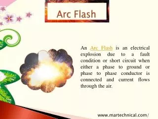
Characteristics of an Arc Flash • When an arc fault occurs, the arc creates a plasma, which has a much lower impedance or much higher conductivity than air • The energy produced melts components, flooding the air with conductive particles • Copper expands to 67,000 times its original volume when vaporized • The flash occurs instantaneously, releasing a huge amount of energy in a very short period of time
Terminology • Which will have the higher current potential? Bolted Arcing • Incident Energy – The energy generated during the arc flash event that is impressed on a surface, such as a human body, at a specific distance from the arc • Faults created by short circuits – • Bolted Fault – current flowing through bolted bus bars or other electrical conductors • Arcing fault – current flowing through the air
Circuit Breaker and Fuse Characteristics • Circuit breakers and fuses are traditionally designed to interrupt rapidly in boltedfault conditions • Arc faults occur at lower current levels • Greater incident energycan be allowed to pass when the current is at a lower value • New device designs will reduce the incident energy Circuit Breaker and Fuse Performance Relating to Fault Currents
Causes of Arc Flash • Mechanical • Accidental touching, dropping of tools or metal parts • Closing into faulted lines • Loose connections
Causes of Arc Flash • Environmental • Dust, impurities, corrosion at contact surfaces • Failure of insulating materials • Snapping of leads due to force – human, rodents or birds
Arc Flash • Thermal impacts of arc flash temperatures 145oF Curable Burn 205oF Cell Death 700oF Clothing Ignition 1,400oF Burning Clothing 1,800oF Metal Droplets 9,000oFSurface of the Sun
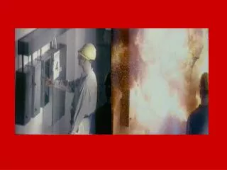
Arc Flash Arc Flash core temperatures can exceed 35,000º F 3rd degree burns form when skin is exposed to 200º F for less than 1/8th of a second Example of an arc fault
Arc Flash Burn • Over 2,000 severe injuries/year • Can kill at distances of 10 ft • Cost of treatment can exceed $1,000,000/case • Does not include litigation fees or process loss • Treatment can require years of rehabilitation • Victim may never return to work or retain quality of life
Arc Blast • High pressure • Copper expands 67,000 times as it vaporizes • Air expands when vaporized • Sound pressure > 160dB (car horn 115dB) • Debris accelerated to 700 mph • People killed with no external sign of injury
Agenda • Electrical Hazards • Codes & Standards • Introduction to NFPA 70E 2009 • NFPA 70E 2009 • Labeling • Safety Program • ‘Live’ Work Permits • Approach and Arc Flash Boundaries • Personal Protective Equipment (PPE) • Minimizing Arc Flash Hazards (Risks)
Codes & Standards • National Electrical Code 2008 -NFPA 70 – 2008 Edition
Codes & Standards • National Electrical Code 2008 -NFPA 70 – 2008 Edition • OSHA 1910 Subchapter S – Occupational Safety & Health Act
Codes & Standards • National Electrical Code 2008 -NFPA 70 – 2008 Edition • OSHA 1910 Subchapter S – Occupational Safety & Health Act • NFPA 70E – Standard for Electrical Safety in the Workplace - 2009
What is NFPA 70E ? • The Standard for Electrical Safety in the Workplace • Referenced in both the NEC and OSHA regulations regarding safe electrical work practices
Agenda • Electrical Hazards • Codes & Standards • Introduction to NFPA 70E 2009 • NFPA 70E 2009 • Labeling • Safety Program • ‘Live’ Work Permits • Approach and Arc Flash Boundaries • Personal Protective Equipment (PPE) • Minimizing Arc Flash Hazards (Risks)
NFPA 70E Covers Electrical Safety in the Workplace • Three Main Sections (2009): • Safety-Related Work Practices • Safety-Related Maintenance Requirements • Safety Requirements for Special Equipment • Arc-Flash is Covered in Section 1, Article 130 (mainly) and Annex D
NFPA 70E 2009 Electrically Safe Work Condition • A state in which the conductor or circuit part to be worked on or near has been: • Disconnected from energized parts • Locked/tagged in accordance with established standards • Tested to ensure the absence of voltage • Grounded if determined necessary
NFPA 70E 2009 • Definitions and formulas to calculate Arc Flash and Shock Hazard Boundaries • Default tables for Arc Flash levels and Personal Protective Equipment (PPE) required for specific tasks • Includes mandates for: • Electrical Safety Program • ‘Live’ Work Permits • Safe Work Practices (including PPE) • Training
NFPA 70E – 2009 Revisions • Removed Chapter 4 – Duplicated NEC • 130.7(C)(5) – Removed exception for Category 0 • Table 130.7(C)(10) – Made Category 1 PPE like Category 2 • No more denim jeans; need FR pants • No more Safety Glasses; need Face Shield • Annex D, Table D.7.4 – Typical working distances • 5 & 15KV Switchgear = 910 mm (36”) • 480V Switchgear = 610 mm (24”) • Other 480V Equipment = 455 mm (18”)
Agenda • Electrical Hazards • Codes & Standards • Introduction to NFPA 70E 2009 • NFPA 70E 2009 • Labeling • Safety Program • ‘Live’ Work Permits • Approach and Arc Flash Boundaries • Personal Protective Equipment (PPE) • Minimizing Arc Flash Hazards (Risks)
Agenda • Electrical Hazards • Codes & Standards • Introduction to NFPA 70E 2009 • NFPA 70E 2009 • Labeling • Safety Program • ‘Live’ Work Permits • Approach and Arc Flash Boundaries • Personal Protective Equipment (PPE) • Minimizing Arc Flash Hazards (Risks)
Labeling Requirement • NFPA 70E 100 (also NEC 110.16 ) Switchboards, panel boards, industrial control panels and motor control centers that are in other than dwelling occupancies and are likely to require examination, adjustment, servicing or maintenance while energized shall be field markedto warn qualified persons of potential electric arc flash hazards. The marking shall be located so as to be clearly visible to qualified persons before examination, adjustment, servicing or maintenance of the equipment.
Labeling Example The Minimum Requirement
Labeling Example Large U.S. Refining Customer
Labeling Example Large Petrochemical Customer
Labeling - Going Forward • The user should establish a labeling philosophy that is consistent throughout the facility and supports their Electrical Safety Program (NFPA 70E-110.7)
How are Arc Flash Levels Determined? • NFPA 70E Provides Two Methods • Tables in Article 130 • These tables tend to place you in Category 2 or 4 and are not the most accurate method. • Calculation • ANNEX D provides various equations to calculate the available Arc Flash Boundaries and Levels • Example: FLASH PROTECTION BOUNDARY (Empirical) • DB = {4.184 CfEn (t/0.2)(610x/EB)}1/x (D.8.5a) • DB = Boundary Distance (mm) • V = System Voltage (KV) • Ibf = Available Short-circuit Current (KA) • t = Seconds • EB = Incident Energy (5.0J/cm2 at Flash Protection Boundary) • These calculations combined with a full survey of all protective devices and fault levels can be used to produce an assessment of the Arc Flash Hazard for your facility.
Single Line Overview ARC FLASH BOUNDARY INCIDENT ENERGY PPE CATEGORY
Agenda • Electrical Hazards • Codes & Standards • Introduction to NFPA 70E 2009 • NFPA 70E 2009 • Labeling • Safety Program • ‘Live’ Work Permits • Approach and Arc Flash Boundaries • Personal Protective Equipment (PPE) • Minimizing Arc Flash Hazards (Risks)
Electrical Safety Program • Employer shall implement an overall Electrical Safety Program • Provides awareness and self-discipline of the potential electrical hazards to employees • Electrical Safety Principles, Controls and Procedures – (Sample Annex E) • Use proper tools • Assess people’s abilities • Identify and eliminate the hazard
Electrical Safety Program • Employer shall implement an overall Electrical Safety Program • Provides awareness and self-discipline of the potential electrical hazards to employees • Electrical Safety Principles, Controls and Procedures – (Sample Annex E) • All equipment is considered energized until proven otherwise
Electrical Safety Program • Employer shall implement an overall Electrical Safety Program • Provides awareness and self-discipline of the potential electrical hazards to employees • Electrical Safety Principles,Controls and Procedures – (Sample Annex E) • Purpose of task • Limits of approach • Equipment details
Electrical Safety Program • Employer shall implement an overall Electrical Safety Program • Provides awareness and self-discipline of the potential electrical hazards to employees • Electrical Safety Principles, Controls and Procedures – (Sample Annex E) • Hazard/Risk Evaluation Procedure – (Sample Annex F)
Electrical Safety Program • Employer shall implement an overall Electrical Safety Program • Provides awareness and self-discipline of the potential electrical hazards to employees • Electrical Safety Principles, Controls and Procedures – (Sample Annex E) • Hazard/Risk Evaluation Procedure – (Sample Annex F) • Job Briefing – (Sample Annex I) • Work procedures involved • Special precautions • PPE requirements
Agenda • Electrical Hazards • Codes & Standards • Introduction to NFPA 70E 2009 • NFPA 70E 2009 • Labeling • Safety Program • ‘Live’ Work Permits • Approach and Arc Flash Boundaries • Personal Protective Equipment (PPE) • Minimizing Arc Flash Hazards (Risks)
‘LIVE’ Work Permits Definition - Safe Electrical Work Practices • Specific practices used to protect employees from the hazards of electricity when working on or near exposed electrical conductors, equipment or circuits parts that are or may be energized • The practices are used when it is infeasible to disconnect (lock or tag out) equipment or circuits from their energy source to perform the work
‘LIVE’ Work Permits Energized Electrical Work • Parts may only be worked on in a live condition if it can be demonstrated that deenergizing them: • Introduces additional or increased hazards • Interruption of life support equipment • Shutdown of hazardous location ventilation equipment • Is infeasible due to equipment design or operational limitations. This includes performing diagnostics and testing
‘LIVE’ Work Permits Is an Energized Electrical Work Permit required? • If live parts are not placed in an electrically safe work condition: • Work to be performed shall be considered energized electrical work • Work shall be performed by written permit only (Sample Annex J)
Energized Work Permit In order to work on the Line Side of the 2000A breaker in this example the permit would look as follows. Some software packages can automatically generate work permits by clicking on the bus you plan to work on.