Plumbing
Plumbing. Typical Plumbing System. Introduction. The residential plumbing system is often taken for granted, but it is an important part of the structure. A complete plumbing system provides an adequate supply of water and removes waste. There are three principal parts: Water supply system.

Plumbing
E N D
Presentation Transcript
Plumbing Typical Plumbing System
Introduction • The residential plumbing system is often taken for granted, but it is an important part of the structure. • A complete plumbing system provides an adequate supply of water and removes waste. • There are three principal parts: • Water supply system. • Water and waste removal system. • Plumbing fixtures.
Typical Drainage System Schematic of a typical water and waste removal system.
Water and Waste Removal Used water and other wastes are carried to the sanitary sewer or septic tank through the waste removal system. These pipes are isolated from the water supply system and must be sized for sufficient capacity, have the proper slope and venting, and have provisions for cleanouts. Typically it is practical to drain as many of the fixtures as possible into a single main drain. The drainage system is not under pressure and depends on gravity to carry the waste to the sewer.
Water and Waste Removal • A vertical drain pipe that collects waste from one or more fixtures is called a soil stack. • Soil stacks that drain water closets are called main stacks. • Every house must have at least one main stack, which is generally 3" in diameter. • Each bathroom must have a main stack. • Stacks that do not drain water closets are called secondary stacks. • Secondary stacks are 1-1/2" diameter.
Water and Waste Removal • Fixtures are connected to the stack using a branch main. • All stacks extend into basement and empty into the house drain. • All structures must have at least one house drain, but may have several. • The house drain becomes the house sewer once it is outside the house. The house sewer empties into the city sanitary sewer or private septic system.
Water and Waste Removal • Gases from the system dissipate through the vent stack—12" above roof. The vent stack provides an air inlet for the drainage system to operate properly • A trap is installed below each fixture to prevent gases from entering the house. The trap is always filled with water. Water closets have a built-in trap. • Each stack requires a cleanout at the base.
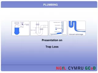
Traps TRAPS The trap most commonly used with plumbing fixtures is the P-trap. The P-trap gets its name because of its general shape-that of the letter P. Traps are required because they prevent sewer gases from entering a building and causing serious illness or death. The term trap seal refers to the water being held in the bent portion of a fixture trap. The trap seal forms a seal against the passage of sewer gases through the trap and into the building.
Traps Examples of P-Traps
House Drain A house drain is the pipe that receives all waste and water discharged by the soil stacks and waste lines. This house drain is laid from a point just outside the building foundation wall where it connects to the house sewer, then through the wall, and either along or under the cellar floor to the point where connection with the soil stack is made. Before laying this drain, determine its overall length and how much pitch to give it so that it will drain as it should.
House Trap Building (house) traps shall be prohibited except where local conditions necessitate such traps. Building traps shall be provided with a cleanout and a relief vent or fresh air intake on the inlet side of the trap. Relief vents or fresh air intake shall be carried above grade and shall be terminated in a screened outlet located outside the building. The size of the relief vent or fresh aid intake shall not be less than one-half the diameter of the drain to which the relief vent or air intake connects.
Cleanouts A plumbing cleanout is a cleanout fitting with a removable plug that is found in a roughed in waste system. It is designed to help keep clear any type of debris that could cause any type of stoppage in the water drain lines. Cleanouts are usually placed at the connection point between the sewer lines and the drain lines where the base is located of a vertical stack and at all places were the pipe direction changes at 90 degrees.
Vents VENTS To prevent the siphonage of a trap seal in fixture traps and allow gravity flow of drainage, you must let atmospheric air from outside the building into the piping system to the outlet (or discharge) end of the trap. The air is supplied through pipes called VENTS. This air provides pressure on the outlet end of the seal equal to pressure on the inlet end. Since the air supplied by the vent to the outlet end provides a pressure equal to that at the inlet end of the trap, the trap seal cannot escape through siphonage. All vent systems should be provided with a main vent or vent stack and a main soil and waste vent. A “main vent” may be defined as the principal artery of the venting system, and vent branches may be connected to the main vent and run undiminished in size as directly as possible from the building drain to the open air above the roof. The term main soil and waste vent, or soil stack vent, refers to the portion of the stack extending above the highest fixture branch. In the figure, this vent extends through the roof. Actually, it is an extension of the main soil and waste stack.
Vents An INDIVIDUAL VENT is a vent that connects the main vent with the individual trap underneath or behind a fixture
Vents A COMMON VENT vents two traps to a single vent pipe. The unit vent can be used when a pair of lavatories are installed side by side, as well as when they are hung back to back on either side of a partition
Riser Diagram Riser diagrams are used as supplementary details on working drawings in order to show more clearly how the plumbing system is to be installed. Riser diagrams of plumbing systems can be shown in both orthographic and isometric views. The most commonly used type of riser diagram for plumbing is the isometric riser diagram. The isometric riser diagram provides a three-dimensional representation of the plumbing system. A riser diagram is not drawn to scale but should be correctly proportioned. The proper use of symbols for the piping and fittings makes it easier to read and interpret the drawing. Typical isometric riser diagram
Riser Diagram Typical elevation riser diagram
Riser Diagram Riser Diagram in elevation
Plumbing Plans • The plumbing plan is a plan view that shows the complete plumbing system. The plumbing plan shows the location, size, and type of all plumbing equipment. • The plumbing plan should include: • Waste lines and vent stacks. • Drain and plumbing fixture locations. • Size and type of pipe to be used. • A plumbing fixture schedule. • Symbols Legend. • General notes. • A plumbing plan is required for each floor of the house.