
Homework Problems
E N D
Presentation Transcript
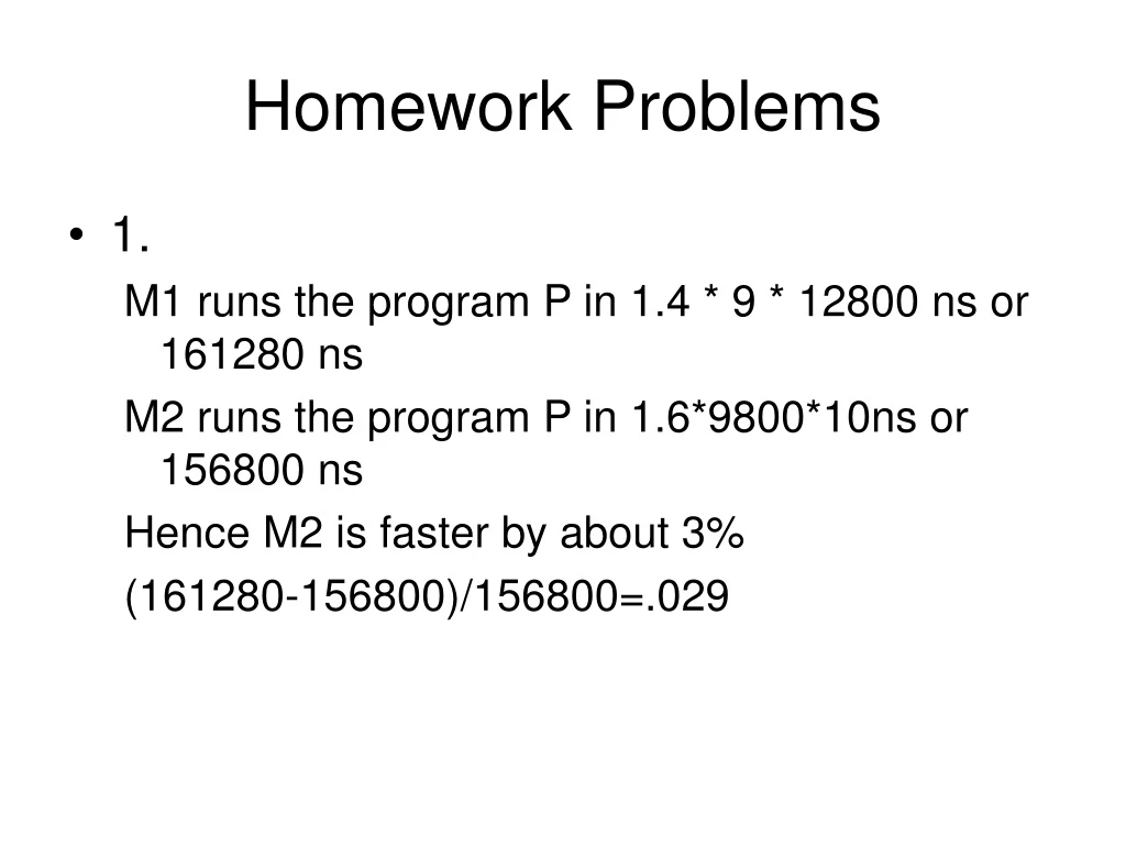
Homework Problems • 1. M1 runs the program P in 1.4 * 9 * 12800 ns or 161280 ns M2 runs the program P in 1.6*9800*10ns or 156800 ns Hence M2 is faster by about 3% (161280-156800)/156800=.029
2.The monks are executing the same program on the same data so it’s SIMD • (or maybe it’s SISD). • 3. 10.3 From text. • PUSH A LOAD E MOV R0, E MUL R0,E,F • PUSH B MUL F MUL R0, F SUB R0,D,R0 • PUSH C STORE T MOV R1,D MUL R1,B,C • MUL LOAD D SUB R1,R0 ADD R1,A,R1 • ADD SUB T MOV R0,B DIV X,R0,R1 • PUSH D STORE T MOV R0, C • PUSH E LOAD B ADD R0,A • PUSH F MUL C DIV R0,R1 • MUL ADD A MOV X, R0 • SUB DIV T • DIV STO X • POP X
11.2 a) 20 b) 40 c) 60 • 11.12 • A. The zero address instruction format consists of an 8-bit opcode and an optional 16 bit address. There are 12 instructions, 7 have an address. • N0=12*8 + 7*16 = 208 bits • B. The one-address instruction consists of an 8-bit opcode and a 16 bit address. There are 11 instructions. • N1=24*11=264 • C. For two address instructions there is an 8 bit opcode and two operands, each of which is 4 bits or 16 bits • N2 = 9*8 + 7*16 + 11*4 = 228 • D. • N3=5*8 + 7*16 + 8*4 = 184 bits
Data and Code are represented as binary words in a computer. • 1 corresponds to some voltage Vcc. Traditionally +5V but newer devices use lower voltages to reduce power and heat. • 0 corresponds to Ground • Third state (unconnected) is also useful for devices, but doesn’t represent a logic level
We’ve seen some examples of instruction sets and bit layouts. • Data will be covered later, but for now we only consider unsigned binary integers and 2’s complement binary integers.
Boolean Algebra • Mathematical underpinnings of digital logic are rooted in Boolean Algebra: • Variables: A,B,C,… have values 1 (True) or 0(False) • Operators: AND, OR, NOT represented respectively by . , +, _ • AND is often just represented by juxtaposition AB instead of A AND B
Truth Tables • Boolean operators and other Boolean Functions can be completely represented by Truth Tables, since their inputs consist of all possible combinations of 0 and 1, ant their output for each combination is either 0 and 1.
Identities • Much of the work of engineers involves finding circuits to implement boolean functions. Since these involve real parts, it’s often necessary to be able to find circuits equivalent to the original circuit. • Transformations can be done using the algebra. The basic identities involved can be verified by proof or simply by truth table.
Functions • A boolean function is a function of boolean variables that takes the values 0 or 1. • We can represent as a formula or a truth table. • Example:
When given in the “Sum of Products” form, the truth table is easily constructed by putting a value of 1 in the rows that correspond to the terms and 0 in other rows. • Conversely, it is easy to go from the truth table to the Sum of Products form by including terms where the value is 1
Since this method seldom gives an “optimal” expression, engineers have over the years developed several methods for simplifying expressions. We can largely ignore these (not being engineers) and assume the work is being done by CAD programs on existing computers. But several methods are discussed in the book.
Algebraic simplification using the identities can reduce the function we had before to a simpler form by noting for example that the first two terms combine to and the first and third combine to give Giving a simplified expression of:
The Quine-McKluskey Method is useful since it lends itself to functions with a larger number of variables than, say Karnaugh maps, and can be programmed relatively easily to give an automatic tool. • It begins by listing the terms in a table in decreasing order of the number of the number of negated terms.
Listing the variables together with a 0 for each negated variable and a 1 for each non-negated variable gives the table on the next slide. Note that the index is the decimal representation of the next 4 columns. • The rows should be considered in groups by the number of 0’s in the row.
We proceed by looking for pairs of terms that differ in exactly one variable. By the way they are arranged we can proceed by starting at the top and looking to pair a term with terms in the next grouping only (terms with 2 negated variables with terms having 1 negated variable) • For each pair found we check the row and combine them to create a new list of terms.
Note that the addition of a 1 to the binary number in a given row of the table always adds a 1, 2, 4, or 8 to the index, greatly simplifying the search. • After all pairs have been found, the process is repeated with the new list of terms together with any unchecked terms, until no new rows are checked.
At this point we have an equivalent expression of • The next step is to try to minimize the expression by creating the table on the next page. X indicates that the row and column are compatible, a circle indicates that it is the only X for a column, a square indicates there’s a circled X in the row.
When all the columns have a marked X we are done (otherwise more processing required) and the final expression corresponds to the circled X’s:
As we work to implement functions, another consideration is the type of gates used. AND, OR, NOT are functionally complete, but NAND gates are also, in the sense that any function can be implemented completely using NAND gates. NOR gates alone are also functionally complete. In some cases the technology may be simpler.
Digital Logic is a useful web page to see the various gates, their implementations in hardware and their uses in computers. This link is also on the home page for the course.
Certain basic functions are useful enough that they are commonly built as standard devices. • The multiplexer connects multiple inputs to a single output, with the selection being controlled by other input bits.
8 to 1 MUX Figure A.9a S0 S1 S2 D0 D1 D2 D3 D4 D5 D6 D7 F
We will implement this in class, but I don’t have a diagram at this point. • Note that Multiplexers can be combined to build larger multiplexers. • Multiplexers can be used to create any boolean function by wiring the inputs to 0 or 1 corresponding to the rows of a truth table.
Other useful devices: • Decoder • Decoder with an enable line • DeMux • PLA • ROM
N-bit gates • Since we often perform operations on multiple bit words, it is important to consider multiple bit gates. For example, an 8-bit AND gate is nothing more than 8 AND gates wired in parallel.
Also with no slides we consider: ½ adder full adder 4-bit adder carry lookahead Subtraction using a 4-bit adder and an XOR gate. We will build a simple 4 function ALU