The Von Neumann Model
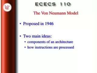
Proposed in 1946 Two main ideas: components of an architecture how instructions are processed. The Von Neumann Model. memory processor input output control unit. Basic Architecture. contains instructions that comprise a program. executes the instructions.

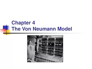
The Von Neumann Model
E N D
Presentation Transcript
Proposed in 1946 Two main ideas: components of an architecture how instructions are processed The Von Neumann Model
memory processor input output control unit Basic Architecture contains instructions that comprise a program executes the instructions orders the execution of the instructions an instruction is a unit of work
Recall the 22 by 3 memory of Ch. 3 more realistically, many PCs are 228 address space (256 MB) 8 bit addressability LC-2 is 216 by 16 Memory
MAR: memory address register location to be read/written MDR: memory data register data value to be read/written what has to be asserted for a value to be written? Special Registers
Contents of Memory/Registers 00 0 1 0 01 1 1 1 10 0 0 1 11 0 0 0 Memory MAR MDR WE 0 0 1 1 1 1 0 0 1 0 1 1 0 1 Causes memory to beread intoMDR 00 0 1 0 01 1 1 1 10 1 1 0 11 0 00 Causes memory to bewritten fromMDR
may contain specialized functional units LC-2 ALU has only ADD, AND, NOT operations size of information processed by ALU is the word length of the computer LC-2 has 16 bit word length Processing Unit
temporary storage used by CPU for intermediate values of computations DEC Alpha has 32 registers LC-2 has 8 (R0-R7) Registers
peripherals that allow computer to be connected to the outside world get data/programs in and out input: keyboard, mouse, scanners, disks output: monitor, printers, disks floppy, hard drives, zip disks, CDs Input/output
keeps track of current instruction in a program and current step in executing an instruction coordinates activities between components registers IR: holds current instruction PC: holds address of next instruction Control Unit
some registers not yet discussed KBSR: status of keys struck KBDR: value of key struck CRTSR: status of monitor CRTDR: value to be written on monitor Discuss LC-2 as an Example ofa Von Neumann Architecture
Instructions and data are both sequences of bits stored in memory One instruction at a time is executed (sequentially) Central ideas of VN architecture
2 parts: opcode: what is to be done operands: what data is manipulated LC-2 instruction: [15:12] opcode [11:0] how to locate operands How many distinct operations in LC-2? Instruction Processing
opcode for ADD is 0001 ADD requires values to be pre-stored in registers, then the result is stored in a register Operands from register2 and register 3, result put in register 1 ADD Example opcode register 1 register 2 not used register 3 15………12 11……………9 8……….….6 5…..……..3 2………...0
load register with a value from memory causes value of 2nd register to be added to offset value, and value at that location is stored in 1st register opcode for LDR is 0110 LDR Example opcode register 1 register2 offset 15………12 11……………9 8…..…….6 5………….0..
LDR cont’d 0110 010 011 000110 15………12 11……………9 8……………….6 5………………….….0 value (2nd register + offset) stored in 1st register contents of memory in location (R3 + 6) goes into R2 called base + offset addressing mode addressing mode: describes the computation needed to yield values for operands
Sequence of steps carried out by control unit to execute instructions called phases 6 phases, all may not be used by each instruction The Instruction Cycle
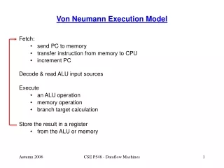
1.fetch: gets next instruction from memory into IR MAR PC MDR contents of memory at location given in MAR IR MDR PC PC + 1 Fetch-Decode-Execute Cycle
2.decode:in LC-2, a 4 to 16 decoder looks at the 4 opcode bits and asserts the appropriate output line to indicate the instruction to be executed 3.evaluate address: if a memory address is to be accessed (as in LDR) this phase computes the address Fetch-Decode-Execute Cycle not needed in ADD
4. fetch operands: obtains values of operands 5. execute: carries out instruction in ALU 6. store result: write result to designated destination Fetch-Decode-Execute Cycle LDR gets value from memory into a register ADD gets values from registers not needed in LDR increment PC, go to 1
2 issues: how to alter the execution order? how to stop at the end of a program? have to change the PC before the next fetch phase Changing the Execution Order
3 kinds of instructions: operate (e.g., ADD) move data (e.g., LDR) control instruction (e.g., JMPR) control instructions load the PC during the execute phase Instruction Types
puts an address in the PC useful for executing loops or skipping around uses base + offset addressing JMPR opcode is 1100 JMPR Example opcode not used register1 offset 15………12 11……………9 8……………….6 5……………….0
1. Initialize a counter to 12 and a sum to 0. 2. If counter is 0, go to step 7. 3. else get next data item; 4. add item to sum; 5. decrement counter; 6. Output “sum is:” sum. 7. End Tying It All Together:Example Algorithm
3000 1 1 1 0 0 0 1 1 0 0 0 0 0 0 0 0 3001 0 1 0 1 0 1 1 0 1 1 1 0 0 0 0 0 3002 0 1 0 1 0 1 0 0 1 0 1 0 0 0 0 0 3003 0 0 0 1 0 1 0 0 1 0 1 0 1 1 0 0 3004 0 0 0 0 0 1 0 0 0 0 0 0 1 0 1 0 3005 0 1 1 0 1 0 0 0 0 1 0 0 0 0 0 0 3006 0 0 0 1 0 1 1 0 1 1 0 0 0 1 0 0 3007 0 0 0 1 0 0 1 0 0 1 1 0 0 0 0 1 3008 0 0 0 1 0 1 0 0 1 0 1 1 1 1 1 1 3009 0 0 0 0 1 1 1 0 0 0 0 0 0 1 0 0 Machine Language Example Corresponding Assembly Language LEA R1, x3100 AND R3, 0 AND R2, 0 ADD R2, 12 BRz R2, x300A LDR R4, M[R1] ADD R3, R4 ADD R1, 1 ADD R2, -1 BRnzp x3004 opcodes
// assumes an array holding 12 integers // has been declared and initialized int sum = 0; for (int i = 0; i < 12; i++) sum = sum + array[i]; C++ Example LEA R1, x3100 AND R3, 0 AND R2, 0 ADD R2, 12 BRz R2, x300A LDR R4, M[R1] ADD R3, R4 ADD R1, 1 ADD R2, -1 BRnzp x3004
Example continued Data memory containing 12 values to sum Register s used 31000 0 0 0 0 0 0 0 0 0 0 0 0 0 0 1 3101 0 0 0 0 0 0 0 0 0 0 0 0 0 0 1 0 3102 0 0 0 0 0 0 0 0 0 0 0 0 0 0 1 1 3103 0 0 0 0 0 0 0 0 0 0 0 0 0 1 0 0 3104 0 0 0 0 0 0 0 0 0 0 0 0 0 1 0 1 3105 0 0 0 0 0 0 0 0 0 0 0 0 0 1 1 0 3106 0 0 0 0 0 0 0 0 0 0 0 0 0 1 1 1 3107 0 0 0 0 0 0 0 0 0 0 0 0 1 0 0 0 3108 0 0 0 0 0 0 0 0 0 0 0 0 1 0 0 1 3109 0 0 0 0 0 0 0 0 0 0 0 0 1 0 1 0 310A 0 0 0 0 0 0 0 0 0 0 0 0 1 0 1 1 310B 0 0 0 0 0 0 0 0 0 0 0 0 1 1 0 0 310C 0 0 0 0 0 0 0 0 0 0 0 0 1 1 0 1 R1 – address of data value R2 – number of data values left to add R3 – Sum of values which have been added R4 – current value to add to the sum
3100 3101 R1 R1 000B 000C R2 R2 0001 0000 R3 R3 0001 0001 R4 R4 Example continued Contents of Registers, first time thru the loop (in hexadecimal) After instruction 3005 After instruction 3008
3101 3102 R1 R1 000A 000B R2 R2 0003 0001 R3 R3 0002 0002 R4 R4 Example continued Contents of Registers, 2nd time thru the loop (in hexadecimal) After instruction 3005 After instruction 3008
3102 3103 R1 R1 0009 000A R2 R2 0006 0003 R3 R3 0003 0003 R4 R4 Example continued Contents of Registers, 3rd time thru the loop (in hexadecimal) After instruction 3005 After instruction 3008
310C 310D R1 R1 0000 0001 R2 R2 004E 0042 R3 R3 000D 000D R4 R4 Example continued Contents of Registers , 12th time thru the loop (in hexadecimal) After instruction 3005 After instruction 3008
When you write C++ programs next quarter, you know they are translated to assembly language by a compiler then translated to machine language to be executed by the hardware hardware consists of functional units in Von Neumann architecture functional units are made up of gates gates are implemented by transistors Foundation for Programming