L BAND HELIX ANTENNA ARRAY
270 likes | 700 Vues
L BAND HELIX ANTENNA ARRAY. VE3NPC. A CONSTRUCTION PAPER. A BIT ABOUT VE3NPC. Not an engineer – a technologist Not a craftsman But fairly successful at constructing things that work. HELIX ANTENNAS. Ideal antenna for home construction Broad band - non critical dimensionally

L BAND HELIX ANTENNA ARRAY
E N D
Presentation Transcript
L BAND HELIX ANTENNA ARRAY VE3NPC A CONSTRUCTION PAPER
A BIT ABOUT VE3NPC • Not an engineer – a technologist • Not a craftsman • But fairly successful at constructing things that work
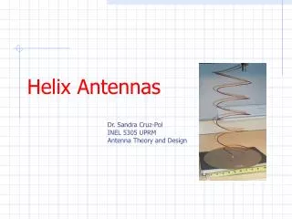
HELIX ANTENNAS • Ideal antenna for home construction • Broad band - non critical dimensionally • I favor a minimum of boom material • Has high side lobes • Deep notch between main and first side lobe
23cm AO-40 SSB ERP • Nominal 1500 watts ERP • Low gain antennas & high power • High gain antenna & low power • Array of 4 X 27 turn helix ants with 10 watts of drive and line loss of 1.25db provides very good operating on L1 uplink
HELIX ANTENNA MATCH • Helix impedance = 140 ohms • Conventional match – fin on conductor • Use 84 ohm ¼ wave matching section to transform to 50 ohms • Circular conductor above a ground plane Z = 138 log 4h/d • Place a ground plane under the 1st quarter turn
HELIX DIMENSION FORMULA • I favor dimensions calculated using formula by Kraus in The Satellite Experimenters Handbook • Circumference = 1 wavelength • Pitch angle = 12.5 degrees
CONSTRUCTION MATERIALS • Conductor – aluminum ground rod wire • Boom and cross braces – fiberglass tension bars (chain link fence) • Reflector – aluminum sheet • Brackets – aluminum angle stock • Machine screws and nuts – stainless steel • Connectors – type N • Match ground plane – hobby brass
4 WAY POWER DIVIDER • Very easy to make • 1 inch square aluminum tubing • ½ inch copper water pipe • type N female chassis connectors • Inside conductor length = odd multiple of a ¼ wavelength
JOINING CABLES • Equal length • Multiple of electrical ½ wavelength from feed point of helix to center conductor of power divider • Minimizes effect of any impedance mismatch
SWR ADJUSTMENT • Adjust match on each ant for min swr with swr meter connected directly to an antenna • If no swr meter use a field strength meter
SPECIFICATIONS Frequency = 1269 MHz Theoretical array gain = 25 dB Circumference = 1 wavelength Probable gain = 23 dB Number of turns = 27 Theoretical beam width = 11deg Pitch angle = 12.5 degrees Ant Gain = 19 dB Spacing between turns = 52.4 mm Helix diameter = 75 mm Beam width = 21 degrees Reflector side = 200 mm
FIBERGLASS TENSION BAR SOURCES • The Home Depot • Love’s • ACE Hardware • True Value • Supplier – Master-Halco Inc.
IN THE REAL WORLD • In use at VE3NPC for about 3 years • Make nearly all of contacts on L uplink • In YB0KTQ QSO party used only mode L and made the most contacts of all entrants • In last FD made 89 SSB and 13 CW using my Yaesu FT-736 with 10 watts and this antenna array
VARIATIONS • Two helix antennas – 20 watts • Two way power divider – center conductor 98 mm (13/32”) brass tube • One helix antenna – 40 watts • For every 3 db increase in feed line loss– need to double the power