The structure development program: Near-term prospects, Contingency planning, Future priorities.
110 likes | 250 Vues
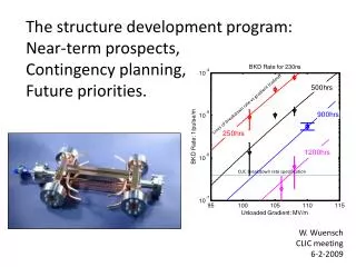
The structure development program: Near-term prospects, Contingency planning, Future priorities. Lines of breakdown rate vs gradient tradeoff. CLIC breakdown rate specification. W. Wuensch CLIC meeting 6-2-2009. CLIC-ILC Cost & Schedule Group (2). Tolerances

The structure development program: Near-term prospects, Contingency planning, Future priorities.
E N D
Presentation Transcript
The structure development program: Near-term prospects, Contingency planning, Future priorities. Lines of breakdown rate vs gradient tradeoff CLIC breakdown rate specification W. Wuensch CLIC meeting 6-2-2009
CLIC-ILC Cost & Schedule Group (2) Tolerances Geometrical and mechanical (alignment and vibration) tolerances are generally tighter with the normal conducting technology “tight mechanical positioning and structure tolerances of the high-frequency, high-gradient machine. In addition, precision components of the module require cooling water of just the right temperature and flow.“ Risk Risk is mitigated through R & D “unveiling of plans for a possible new 6.5-GeV two-beam system test facility in the future. Many of the issues facing the ILC team who work with the four ILC system test facilities - are present with this new CLIC test facility also. It will be a challenge for us all to make sure we use resources effectively to build test facilities that are both convincing and effective demonstrations of the technology and scientific instruments in their own right.” Cost & Schedule Group must account for these kinds of issues CLIC / ILC (mcr)
Let’s focus for a moment on just six of the structures, If any one of these test structures is clearly successful, then we will have demonstrated feasibility – results are expected by mid year. Baseline fabrication technique
A positive outcome means that we still have LOTS of work to do, but the situation is straightforward, and I will return to this contingency later (slide 9 in fact). We believe we will have a positive outcome because two T18 disks have worked well, the (smaller) damping features of the NLC/JLC structures did not affect high-gradient performance and a detailed analysis of the quadrant data indicates their (smaller) damping features did not affect performance (no time to go into this now). But a negative outcome on all of the six structures means that we have a problem which is either, Fundamentalor Technological
Fundamental first Good T18 results and bad TD18 results implies that the problem lies in the D. For example this could come from a rearrangement of fields that result in focused breakdown currents which inflict more damage (HDX11?). This kind of effect is outside the scope of our scaling laws but will be addressed by the combined work of Olexey 3 (fellow who will work for Alexej 1), the advanced computation group at SLAC (Kwok Ko, Zenghai Li, Arno Candel) and our Finnish multi-scale colleagues (Helga, Kai and Flyura). We would first try to confirm the origin of anomalous behavior with inspections like SEM. We have CD10 test structures in the pipeline to check the waveguides in a simple configuration. Anybody have any bright ideas for diagnostics on how to see where in cell the breakdowns make trouble?
Fundamental - alternatives Fully slotted-iris quadrant design. The slots allow us to close the waveguide opening, to sizes like NLC/JLC. Quadrants have of course proven challenging… Roger Jones and Vasim Kahn are working on adapting the DDS (like NLC/JLC) concept to 100 MV/m. It is likely that this will require a larger bunch spacing than we have now and consequently lower efficiency - unless we have the tolerances for zero crossings. A CLIC DDS design is an FP7 activity. Valery’s first try at a choke mode cavity didn’t work very well. However Alexej has proposed a new configuration which will be implemented in a CD10-choke. Choke mode cavities probably need larger bunch spacing - we will study a choke mode CLIC design in a collaboration with Tsinghua University and build a prototype.
Fundamental - alternatives Reduced waveguide opening, and just pay the price on efficiency through increased bunch spacing. New materials, real progress in dc spark, will result in a new test structure at an appropriate moment. Other ideas – stay tuned n.b. These alternatives are generally consistent with improved pulse surface heating.
Technological Damped disks are an extrapolation of an existing technology – no way around this. As we have seen - materials and quadrants (and maybe PETS too) - changes in technology can have significant effects when you are trying to run close to performance limits. Early attempts at 30 GHz damped disks did not work out well (already for machining) which is one of the reasons we pursued quadrants. A basic difficulty we had is that good contact between disks requires flatness (or flexibility). The bigger diameter required makes total flatness harder plus milling in waveguides screws up flatness due to induced and relieved stress during machining. X-band is easier and there is progress. KEK now
Technological • If we do face a technological problem, we hope that we will be able to identify its origin by inspecting test structures. We will soon see how successful we are at this procedure with the CERN built T18. • A solution should then be possible, but working out the bugs may take a few iterations, n*6 months/η*parallelism, and will require a lot of patience. • We try to cut down the time associated with technology risk by fabricating at CERN and KEK in parallel (SLAC only makes undamped structures) and carrying forward two basic assembly technologies, vacuum and hydrogen brazing. More collaborators (like Fermilab) are welcome… • In my personal opinion, the quadrants currently face technological problems (again no time to go into details now). • By investigating the alternatives listed in the previous section, we may find a solution which has a technology that is easier to get going sooner – double purpose. • And in parallel we will continue with the undamped structure program.
Do you really need me to tell you what we will do if one of the tests work well? Our next moves following a success: Reproduce the structure and (hopefully) the results. Say four times. Move from TD18 to TD24(CLIC_G) if the first success is a TD18 – that is, move to a better optimized geometry. Repeat more times. Address pulsed surface heating (tricky subject). Do the C10s to get scaling better and move closer to optimum. Prove shorter coupler. Repeat. Add damping materials. Follow up new ideas which give higher performance – materials, recirculation, all the alternative stuff etc. Check dynamic vacuum levels (beam dynamics), tolerances, etc. Post-success planning being defined for the TDR task force, with presentation next week.
“There are known knowns. There are things we know that we know. There are known unknowns. That is to say, there are things that we now know we don’t know. But there are also unknown unknowns. There are things we do not know we don’t know.” Donald Rumsfeld I’ve tried to cover most of our know-unknowns, but no doubt unknown-unknowns lurk, (why did the first T18 deteriorate after 1200 hrs, making it now a semi-known-unknown?) Anyway we have a good chance to show gradient feasibility by summer.