Download
1 / 51
510 likes | 531 Vues
This meeting discusses methods for correcting spatial inhomogeneities of the absolute energy scale in EPIC calibration, including offsets in the energy scale, column gain variations, and CTI changes due to residual light through the ventilation hole.

E N D
Correcting spatial inhomogeneities of the absolute energy scale EPIC Calibration & Operations Meeting Madrid, 2010 March 23-24
EPIC-Cal Meeting, MPE-Garching, Germany, 2006 May 4 20 adu image, rev 546 Correcting spatial inhomogeneities of the absolute energy scale • offsets in the energy scale due to errors in the offset map • column gain variations after launch • CTI changes due to residual light through the ventilation hole
Correcting spatial inhomogeneities of the absolute energy scale • offsets in the energy scale due to errors in the offset map • column gain variations after launch • CTI changes due to residual light through the ventilation hole EPIC-Cal Meeting, Mallorca, Spain, 2007 Nov 6-7
Correcting spatial inhomogeneities of the absolute energy scale • offsets in the energy scale due to errors in the offset map • column gain variations after launch • CTI changes due to residual light through the ventilation hole EPIC-Cal Meeting, Mallorca, Spain, 2007 Nov 6-7
Correcting spatial inhomogeneities of the absolute energy scale • offsets in the energy scale due to errors in the offset map • column gain variations after launch • CTI changes due to residual light through the ventilation hole EPIC-Cal Meeting, Mallorca, Spain, 2009 March 31 – April 1
Vela SNR: extended source with bright OVII emission excellent calibration source 2001- 2007: 12 long FF observations, several with different pointing coordinates and roll angles fairly homogeneous illumination of the detector
Superposition of all Vela SNR observations in FF mode 0.40 – 0.74 keV photon map (singles) exposure map maximum: 172 singles/pixel total exposure (after removing times of background flares): ~300 ks exposure corrected map
Internal calibration source onboard XMM-Newton / EPIC-pn Al-K Mn-K inhomogeneous irradiation at Mn-K, illumination of quadrant 3 very poor
Superposition of all Vela SNR observations in FF mode 0.40 – 0.74 keV photon map (singles) exposure map maximum: 172 singles/pixel total exposure (after removing times of background flares): ~300 ks exposure corrected map
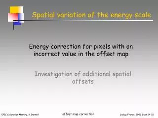
Spatial properties of the absolute energy scale 0.40 – 0.74 keV photon map (singles) adaptive binning into subareas of similar signal
Spatial properties of the absolute energy scale vertical binning according to response matrices horizontal binning adaptively, criterion: ~5000 single events within 400 – 740 eV (above background) 422 fields
Preparations for a joint fit removal of periods of enhanced background correction for local energy shifts due to errors in the offset map (epreject) correction for energy shifts between the individual observations correction for out-of-time events
Spectral model used ( E = 0.43 – 0.74 keV ) all line energies and widths coupled to reference line (O VII r) relative line fluxes of O VII triplet fixed continuum approximated by powerlaw 8 fit parameters
result: energy scale spatially homogeneous within ±10 eV however, also evidence for systematic shifts in a ring-like pattern mean 1σ error in line energy: 1.8 eV
Preparations for a joint fit removal of periods of enhanced background correction for local energy shifts due to errors in the offset map (epreject) correction for energy shifts between the individual observations correction for out-of-time events
Preparations for a joint fit removal of periods of enhanced background correction for local energy shifts due to errors in the offset map (epreject) correction for energy shifts between the individual observations correction for out-of-time events default in SAS: PI binned with 5 eV resolution
Preparations for a joint fit removal of periods of enhanced background correction for local energy shifts due to errors in the offset map (epreject) correction for energy shifts between the individual observations correction for out-of-time events special switch in SAS: PI binned with 1 eV resolution
“before”: 5 eV resolution in PI correction 54 dof 0.43 – 0.74 keV mean 1σ error in line energy: 1.8 eV
“after”: 1 eV resolution in PI correction 59 dof 0.40 – 0.74 keV mean 1σ error in line energy: 1.6 eV
Merged Vela SNR observations (flag = 0, pattern = 0) original data
Merged Vela SNR observations (flag = 0, pattern = 0) after applying the energy corrections (same binning!)
Merged Vela SNR observations (flag = 0, pattern = 0) after applying the energy corrections (different binning!)
Applying the energy shifts derived from Vela observations to Al-K (calclosed exposure in rev 0080):
Applying the energy shifts derived from Vela observations to Al-K (calclosed exposure in rev 0080): “before”
Applying the energy shifts derived from Vela observations to Al-K (calclosed exposure in rev 0080): “after”
Applying the energy shifts derived from Vela observations to Mn-K (calclosed exposure in rev 0080):
Applying the energy shifts derived from Vela observations to Mn-K (calclosed exposure in rev 0080): “before”
Applying the energy shifts derived from Vela observations to Mn-K (calclosed exposure in rev 0080): “after”
EPIC pn: “front side”, image flipped and enlarged EPIC pn: “front side”, image flipped, enlarged and rotated
EPIC pn: “front side”, image flipped, enlarged and rotated CCD 4
EPIC pn: “front side”, image flipped, enlarged and rotated CCD 4
EPIC pn: “front side”, image flipped, enlarged and rotated CCD 4 Ge-L, CCD 4
EPIC pn: “front side”, image flipped, enlarged and rotated CCD 4 Ge-L, CCD 4
CCD 4 Ge-L, CCD 4 EPIC pn: “front side”, image flipped, enlarged and rotated EPIC pn ground calibration Ge-L CCD 4
EPIC pn ground calibration Fe-K CCD 4
EPIC pn ground calibration Ge-K CCD 4
Deviations from spatially constant (but energy dependent) CTI per column (EPIC pn ground calibration at Orsay) ~ 1.3 % (15 eV) ~ 0.4 % (25 eV) ~ 0.35 % (35 eV) EPIC pn ground calibration: no CTI maps at all below 0.7 keV (Fe-L) no good CTI maps below 1.2 keV (Ge-L) good CTI maps at 1.2 keV (Ge-L), 6.4 keV (Fe-K), 8.0 keV (Cu-K), 9.9 keV (Ge-K)
OVII 0.57 keV Deviations from spatially constant (but energy dependent) CTI per column (EPIC pn ground calibration at Orsay) ~ 1.8 % (10 eV) ~ 1.3 % (15 eV) ~ 0.4 % (25 eV) ~ 0.35 % (35 eV) EPIC pn ground calibration: no CTI maps at all below 0.7 keV (Fe-L) no good CTI maps below 1.2 keV (Ge-L) good CTI maps at 1.2 keV (Ge-L), 6.4 keV (Fe-K), 8.0 keV (Cu-K), 9.9 keV (Ge-K)
Merging ground and in-orbit CTI determinations .. .. to be continued ..