Download
1 / 37
370 likes | 488 Vues
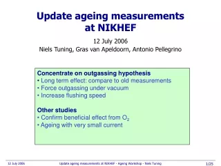
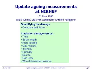
This document details updates on the ageing measurements conducted at NIKHEF, focusing on the quantification of damage observed in irradiated modules. It highlights the differences between irradiation damage and time effects, and discusses the various factors affecting these measurements, such as gas mixture composition, humidity, and high voltage conditions. Recommendations include continued testing with various gas mixtures and outgassing assessments to enhance understanding of damage impacts. The results show linear gain loss with irradiation time, and strategies for future testing are proposed.

E N D
Update ageing measurementsat NIKHEF • Quantifying the damage • Compare definitions • Irradiation damage versus: • Time • Straw length • High Voltage • Gas mixture • Intensity • Humidity • Source • Gas Flow • Wire (transverse position) 31 May 2006 Niels Tuning, Gras van Apeldoorn, Antonio Pellegrino Update ageing measurements at NIKHEF - LHCb week - Niels Tuning
Recommendation Ageing Workshop (3 April) Checked Checked • Outgassing: • Check effect after long term (3-4 weeks) flushing • Heat module to 35 – 40 oC • Gas mixture: • Try Ar/CO2/O2 70/27/3 (TRT-like) • Add water (> 5000 ppm) • Processing: • Training procedure under N2 flushing with ~µA currents and with normal/reverse bias • Sputter chambers with Ar/O2 99/1 • Burning procedure with reverse voltage (cure, prevent?) • Improve knowledge of phenomenon: • Continue irradiation to see if gain decrease levels off • Large area irradiation • Built new test module with minimal components • SEM/EDX • Straw • Clean wire Checked; See HD This talk < 2000ppm Checked; need follow up Checked to < 300 hrs Checked: link ; pursued in HD Update ageing measurements at NIKHEF - LHCb week - Niels Tuning
Recommendation Ageing Workshop (31 May) This talk This talk This talk • General comment: • compare HD – NIKHEF, agree on quantifying effect • Gas mixture: • Continue Ar/CO2/O2 70/27/3 • vary O2 percentage • Long term > 100 hr • Cure old damages? • Processing: • Training procedure under N2 or CO2 flushing with ~µA currents and with normal/reverse bias • Burning procedure with reverse voltage > 200hr • Improve knowledge of phenomenon: • Confirm gas flow dependence • Verify if maximum ageing is at 2nA/cm • Large area irradiation at GIFF; check for Malter effect • Outgassing: • Continue outgassing tests of glue, lubricant. Update ageing measurements at NIKHEF - LHCb week - Niels Tuning
Compare HD test module to F-module • Conditions: • Flow: Ar/CO2 20 l/hr • VF/VHD = 45 • Linear gas velocity in straw • F-mod: 9 cm/min • HD-mod: 72 cm/min Gas flow 23 hrs (test 4) • So, some ratios…: • Irradiation time: x13 • Linear flow: x8 • Damage: x1/3 F-module 1/3? Define ‘damage’! 293 hrs HD-module Update ageing measurements at NIKHEF - LHCb week - Niels Tuning
Quantifying the damage Remember: 1 pixel = 1 straw x 1cm = 0.5x1 cm2 • Normalize the ratio plot: • around the damage ≡ 1 Make rings around source position: Update ageing measurements at NIKHEF - LHCb week - Niels Tuning
Quantifying the damage • HD definition • biggest avg damage of a ring • Max damage • Avg damage of 2 worst pixels • Summed damage • Add damage of each pixel Average gain loss Integrated gain loss Question: which ring has more damage: R1 or R3? Update ageing measurements at NIKHEF - LHCb week - Niels Tuning
Damage vs time – HD module • Conditions: • 20 l/hr • Plot relative current vs netto irradiation time • Corrected for atmospheric pressure • ΔI/I=-7.5Δp/p • Conclusions: • Gain drops linear with irradiation time Gain drop vs irradiation time shown for 6 points: Relative gain Irradiation time (hrs) Update ageing measurements at NIKHEF - LHCb week - Niels Tuning
Damage vs time – F-module 3 • Conditions: • 20 l/hr • Plot relative current vs netto irradiation time • Corrected for atmospheric pressure • ΔI/I=-7.5Δp/p • Conclusions: • Gain drops linear with irradiation time Gain drop vs irradiation time shown for 6 points Relative gain Irradiation time (hrs) Update ageing measurements at NIKHEF - LHCb week - Niels Tuning
Damage vs time • Conclusions: • No sign of reaching a plateau? II. Max damage (avg of 2 pixels) III. Summed damage (add every pixel) Relative gain I. HD definition (worst avg ring) Update ageing measurements at NIKHEF - LHCb week - Niels Tuning
Module 3 – side ATest straw length dependence Gas flow 1: 19hr 2: 21hr • Conditions: • Flow: Ar/CO2 20 l/hr • 2mCu, 90Sr source • ~23 hours of irradiation • Test 2: problem with CO2: • 21 hours normal operation • 15 min no CO2 with large current Initially low current at repaired spot… H20? 3: 23hr 4: 23hr • Conclusions: • Damage looks very similar along the straw: no straw dependence 5: 23hr 6: 19hr Update ageing measurements at NIKHEF - LHCb week - Niels Tuning
Module 3 – side ATest straw length dependence Before After 3: 23hr 5: 23hr 6: 19hr 1: 19hr 4: 23hr 2: 21hr wire locator wire locator Update ageing measurements at NIKHEF - LHCb week - Niels Tuning
Damage vs position • Conclusions: • No position dependence • Conclusions: • Dependence on impurity? Flushing helps II. Max damage (avg of 2 pixels) III. Summed damage (add every pixel) I. HD definition (worst avg ring) • Conclusions: • Dependence on humidity? Update ageing measurements at NIKHEF - LHCb week - Niels Tuning
Vary HV: 1450, 1600, 1800V 21 hrs, 1450V • Conditions: • Flow: Ar/CO2 20 l/hr • 2mCu, 90Sr source • Ar/CO2 70/30 • At 1800 V, source further from surface same current profile • Conclusions: • No HV dependence 21 hrs, 1600V (test4) 21 hrs, 1800V Current profile similar: Update ageing measurements at NIKHEF - LHCb week - Niels Tuning
Damage vs HV • Conclusions: • No HV dependence Update ageing measurements at NIKHEF - LHCb week - Niels Tuning
Long term 1450V Gas flow 18 hrs, 1450V • Conditions: • Flow: Ar/CO2 20 l/hr • 2mCu, 90Sr source • Ar/CO2 70/30 • Conclusions: • Running at lower HV does not save us… 18+52 hrs, 1450V Current profile during irradiation: 18+52+19 hrs, 1450V Update ageing measurements at NIKHEF - LHCb week - Niels Tuning
Damage vs time • Conclusions: • Damage at 1450 V deeper (NB with 4x smaller current) 1450 V, 30nA 1600 V, 130nA Update ageing measurements at NIKHEF - LHCb week - Niels Tuning
1450 V:Does it scale with the accumulated charge? • Conclusions: • Lower acceleration factor, higher damage 21 hrs, 1450V 4x the irradiation time, ¼ x current: 1.5x more damage: 89 hrs, 1450V Update ageing measurements at NIKHEF - LHCb week - Niels Tuning
1450 V: Maximum damage depends at 10nA • Conclusions: • Max damage around ~ 5-10nA? Update ageing measurements at NIKHEF - LHCb week - Niels Tuning
Vary Intensity NB: different scale 19 hrs, low int • Conditions: • Flow: Ar/CO2 20 l/hr • 2mCu, 90Sr source • 1600V, 70/30 • Conclusions: • 3 times the intensity, same damage? 22 hrs, default (test16) 19 hrs, high int Current profile differs: Update ageing measurements at NIKHEF - LHCb week - Niels Tuning
Damage vs Intensity • Conclusions: • No intensity dependence?? Update ageing measurements at NIKHEF - LHCb week - Niels Tuning
Vary CO2: 80/20, 70/30, 60/40 21 hrs, 80/20 • Conditions: • Flow: Ar/CO2 20 l/hr • 2mCu, 90Sr source • 1600V • At 80/20 V, source further from surface similar current profile • NB: 60/40 higher current, shorter irradiation… • Conclusions: • More argon, more damage? 21 hrs, 70/30 (test2) 16 hrs, 60/40 Current profile similar: Update ageing measurements at NIKHEF - LHCb week - Niels Tuning
Damage vs CO2 percentage • Conclusions: • Less CO2, more Argon more damage • NB: 60/40 was run at twice the current. Update ageing measurements at NIKHEF - LHCb week - Niels Tuning
Vary Humidity3, 600, 2000 ppm 22 hrs, 3 ppm (test16) • Conditions: • Flow: Ar/CO2 20 l/hr • 2mCu, 90Sr source • 1600V , Ar/CO2 70/30 • Conclusions: • No humidity dependence? 22 hrs, 600ppm 15 hrs, 2000ppm Update ageing measurements at NIKHEF - LHCb week - Niels Tuning
Damage vs Humidity? • Recall discussion on position dependence, slide10; fake humidity dependence? • Conclusions: • No humidity dependence? Update ageing measurements at NIKHEF - LHCb week - Niels Tuning
Effect of humidity - without irradiation • Humidity increased: from 2 ppm to 2500 ppm Ratio scans: 19May / 8May • Humidity decreased: from 2500 ppm to 70 ppm Ratio scans: 28May / 19May Conclusion: • Humidity changes conductivity of layer? • But doesn’t remove it… Ratio scans: 28May / 8May Update ageing measurements at NIKHEF - LHCb week - Niels Tuning
Confirm Gas Flow Dependence NB. different scale • Conditions: • Flow: Ar/CO2 70/30 • 2mCu, 90Sr source • 1600V • 20 l/hr vs 5 l/hr • Conclusions: • Gas flow dependence confirmed 19 hrs, 5 l/hr 19 hrs, 20 l/hr (test 6) Update ageing measurements at NIKHEF - LHCb week - Niels Tuning
Damage vs Gas Flow • Conclusions: • Larger gas flow larger damage Update ageing measurements at NIKHEF - LHCb week - Niels Tuning
Confirm Center vs Side difference NB. different scale • Conditions: • Flow: Ar/CO2 70/30 • 2mCu, 90Sr source • 1600V • center vs side • Conclusions: • Center vs side difference confirmed 18 hrs, side 19 hrs, center (test 6) Update ageing measurements at NIKHEF - LHCb week - Niels Tuning
Damage: Side vs Center • Conclusions: • More at the side less damage Update ageing measurements at NIKHEF - LHCb week - Niels Tuning
Vary Source: 90Sr versus 55Fe • Conditions: • Flow: Ar/CO2 20 l/hr • 1600V, 70/30 • 90Sr versus 55Fe • Conclusions: • 90Sr irradiation: • x2 current • x3/4 irradiation time • Expect: 1.5x damage • Observe: 1.5x damage • 90Sr and 55Feage equally for the same acc. Charge? 22 hrs, 90Sr (test16) 30 hrs, 55Fe Current profile differs: x2: Update ageing measurements at NIKHEF - LHCb week - Niels Tuning
55Fe Comparison NIKHEF – HD Agreement? HD NIKHEF Update ageing measurements at NIKHEF - LHCb week - Niels Tuning
Compare large area irradiation • HD: 9 keV X ray, radius ~50cm, 140 hrs, 50 nA (1520V): 80% damage • NI: 2mCu 90Sr, radius ~30cm, 14 hrs, 50 nA (1600V): 10% damage • Both: damage upstream, • Both: more damage in the center of the module gas Update ageing measurements at NIKHEF - LHCb week - Niels Tuning
Conclusions • Quantifying the damage • What definition shall we use? • Irradiation damage versus: • Time • Straw length • High Voltage • Gas mixture • Intensity • Humidity • Flow • No plateau? • No dependence • No dependence • More Ar more damage? • No dependence? • No dependence • More flow more damage Smaller acceleration factor, larger damage Update ageing measurements at NIKHEF - LHCb week - Niels Tuning
Plans at NIKHEF • Outgassing: • Heat module to 35 – 40 oC • Gas mixture: • Try Ar/CO2/O2 70/27/3 (TRT-like) • vary O2 percentage • Long term > 100 hr • Add more water (> 5000 ppm) • Processing: • Training procedure under N2 or CO2 flushing with ~µA currents and with normal/reverse bias • Sputter chambers with Ar/O2 99/1 • Burning procedure with reverse voltage > 200hr • Improve knowledge of phenomenon: • Built new test module with minimal components • Continue outgassing tests of glue, lubricant. Update ageing measurements at NIKHEF - LHCb week - Niels Tuning
TOF SIMS at Philips • What is TOF SIMS? • Time-of-Flight Secondary Ion Mass Spectroscopy • What can it see? • (Part of) molecules • positively charged or • negatively charged • Only the top layer (<1 nm) • Same three samples: • “Dirty”:Irradiated sample • “Clean”:Same wire, but not irradiated • “New”:New wire Update ageing measurements at NIKHEF - LHCb week - Niels Tuning
Conclusions from Philips • The carbon signals are detected with high intensities. • The highest amount is found on the “dirty” wire. • As can be seen in the negative mode, the carbon concentration is significantly increased after SE sputtering, indicating a severe carbon deposit. • After cleaning the surface of the “clean” surface (with high ion current), most of the carbon contamination was removed. This means that the organic contamination on the “clean” surface is < one monolayer. This is supported by the fact that a Au-peak is visible in the spectrum with relatively high intensity. • Na • The “dirty” wire contain a high amount of sodium (Na). • The “clean” wire contain a lower concentration. After cleaning the surface by SE sputtering, still a lot of Na is detected. • Na is also detected on the kapton material (both on the yellow and black areas). • K, Ca and Fe are detected on the kapton material with relatively high intensities. • These elements are detected on the “clean” and “dirty” wires too. After SE imaging (sputtering the surface) still a high amount is present. • CN • The kapton material contains a high concentration of a nitrogen containing organic compound (see e.g. CN-, NOx- concentration). • A high concentration of these fragments is detected on the “clean” and “dirty” wires. After cleaning the surface of the “dirty” wire after SE sputtering, the amount of CN- species is greatly enhanced. • It has to be noted that the CN- concentration detected on the “new” wire is associated with the high Au signal. Update ageing measurements at NIKHEF - LHCb week - Niels Tuning
Conclusions from Philips (2) Conclusions: By TOF-SIMS it is shown that the surface of the “new” wire is rather clean. The “clean” wire is slightly contaminated by a nitrogen containing organic compound. Furthermore, the “clean” wire is slightly contaminated by polydimethylsiloxane (Si oil). The “dirty” wire is strongly contaminated by the N-containing organic compound. The TOFSIMS measurements indicate that the carbon layer must be relatively thick. After cleaning the surface by SE sputtering the amount of C, CN-, Cl-, F-, POx- elements/compounds increases significantly. The “dirty” wire contain a high amount of Na, K and Ca. The detected inorganic/organic elements/compounds might be associated to the kapton XC/Al material. By surface TOFSIMS it is not possible to detect the exact composition and thickness of the thick carbon layer. XPS (X-ray photon electron spectroscopy) might be more suitable to determine the chemical composition of the carbon layer (information depth is 5 nm). Update ageing measurements at NIKHEF - LHCb week - Niels Tuning