Download
1 / 22
230 likes | 438 Vues
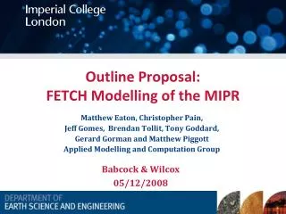
Outline Proposal: FETCH Modelling of the MIPR. Babcock & Wilcox 05/12/2008. Matthew Eaton, Christopher Pain, Jeff Gomes, Brendan Tollit, Tony Goddard, Gerard Gorman and Matthew Piggott Applied Modelling and Computation Group. Team Members.

E N D
Outline Proposal: FETCH Modelling of the MIPR Babcock & Wilcox 05/12/2008 Matthew Eaton, Christopher Pain, Jeff Gomes, Brendan Tollit, Tony Goddard, Gerard Gorman and Matthew Piggott Applied Modelling and Computation Group
Team Members • Dr Matt Eaton (RT and Uncertainty Analysis) – Principal Investigator • Prof Chris Pain (Numerical Analysis and Multiphysics) – Head of the AMCG and Co-I • Prof Tony Goddard (RT and Reactor Physics) – Senior Adviser and Co-I • Dr Matt Piggott (CFD and Turbulence) – Co-I • Dr Gerard Gorman (Parallel Mesh Adaptivity and QA) – Co-I • Dr Jeff Gomes (Multiphysics and CMFD) – Funded PDRA • Mr Brendan Tollit (Multiphysics and Reactor Physics) – Funded PDRA
Coupled CMFD and RT Models: FETCH WIMS9 Tabulated Group Constants
Control Rod Water Inlet Water Outlet Sweep Gas Inlet Uranium Solution Inlet Sweep Gas Outlet Reactor Vessel Mist Eliminator Uranium Solution Cooling Coils Reflector (Sectioned) Uranium Solution Drain MIPR
Goals • Investigation of transient fault modelling of the MIPR’s under numerous prescribed conditions • Investigating MIPR’s stability at high power densities
Challenges • 3D Complex Geometry – heterogeneous modelling • Phase change – Boiling and Condensation • Parameterisation of the radiolytic gas bubbles nucleation on the cooling coil and submerged surfaces • Large Scale Fully-Coupled RT/CMFD-TH • Automated and Continuous QA
Work-Packages • WP1:Neutronics modelling of MIPR and 50KW Operational reactor • WP2:Development of 2-D RZ and 3-D non-explicit geometry coupled RT/CMFD-TH MIPR model • WP3:Initial 50KW test cases and Accident scenarios for 2-D RZ and 3-D non-explicit geometry
Work-Packages • WP4:Large Scale Modelling using FETCH and parallel visualization interfacing with PARAVIEW • WP5:Development of a 3-D explicit geometry coupled RT/CMFD-TH MIPR model and a 50KW fully operational test-case • WP6:Initial 50KW test-cases and Accident scenarios for 3-D explicit geometry model of the MIPR • WP7:Automated QA, RT/CMFD-TH Interfaces, Documentation and Deliverables
WP1:Neutronics Modelling of MIPR and 50KW Operational Reactor • Task 1:Development of 2-D axi-symmetric RZ model and 3-D non explicit geometry (parameterization of control rods and cooling coils) with nuclear cross-section data generated using WIMS • Task 2:Development of a 3-D explicit geometry model of the MIPR using GID and RHINO and explicit sub-group spatial/energy self-shielding phenomena in FETCH • Task 3: Interfacing FETCH with the SCALE US NRC criticality code for generation of nuclear data for the MIPR
WP2:Development of 2-D RZ and 3-D non-explicit geometry coupled RT/CMFD-TH MIPR model • Task 1: Parameterization of the heat transfer aspects of the cooling coils • Task 2:Parameterization of the radiolytic gas bubble nucleation on cooling coil and control rod surfaces and within the solution volume of the MIPR • Task 3: Parameterization of homogeneous and heterogeneous (submerged surfaces) boiling
WP3:Possible 50KW test cases and Accident scenarios for 2-D RZ and 3-D non-explicit geometry • 1: Inadvertent withdrawal of control rods • 2:Introduction of excess fuel into solution • 3: Changing the fuel U/H ratio by introducing hydrogenous (excess acid, coolant tube leak etc) material into the solution core • 4:Increased fuel solution density due to rise of dome pressure or drop of fuel temperature
WP3:Possible 50KW test cases and Accident scenarios for 2-D RZ and 3-D non-explicit geometry (cont) • 5:Fuel solution leakage • 6:Hydrogen deflagration and/or detonation • 7: Overpower without scramming of control rods • 8: Loss of pumping power
WP4: Parallel FETCH interface and parallel visualization interfacing with PARAVIEW • Task 1:Interface module of CMFD/RT parallelisation • Task 2: Distributed and multi-core processor testing on ICT facilities. • Task 3: Parallel visualization
WP5: Development of a 3-D explicit geometry coupled RT/CMFD-TH MIPR model and a 50KW fully operational test-case • Task 1: Parameterization of the nucleation on cooling coil and control rod surfaces and within the solution volume of the MIPR • Task 2:Parameterization of homogeneous and heterogeneous (submerged surfaces) boiling
WP6: Possible 50KW test-cases and Accident scenarios for 3-D explicit geometry model of the MIPR (repeated from previous) • 1: Inadvertent withdrawal of control rods • 2:Introduction of excess fuel into solution • 3: Changing the fuel U/H ratio by introducing hydrogenous (excess acid, coolant tube leak etc) material into the solution core • 4:Increased fuel solution density due to rise of dome pressure or drop of fuel temperature
WP6: Possible 50KW test-cases and Accident scenarios for 3-D explicit geometry model of the MIPR (cont) • 5:Fuel solution leakage • 6:Hydrogen deflagration and/or detonation • 7: Overpower without scramming of control rods • 8: Loss of pumping power
WP7: Automated QA and RT/CMFD-TH Interfaces and Documentation • Task 1:Verification and Validation Suite Procedures – Bubbly solutions initial benchmarks (TRACY, SILENE, Aparatus B, CRAC, etc) • Task 2:Users-orientated interface for the RT and CMFD-TH Modules: Spud-Diamond and CAD-based Mesh-generator • Task 3: Automated and Continuous QA: SVN, Buildbot • Task 4: Complete Wiki-based documentation
Control Rod Water Inlet Water Outlet Sweep Gas Inlet Control Rods Uranium Solution Inlet Cooling Coils Reactor Vessel Sweep Gas Outlet Mist Eliminator Uranium Solution Sweep Gas Diffuser Cooling Coils Cross Section View Uranium Solution Drain Full Assembly Explicit Heterogeneous Modelling
Explicit Heterogeneous Modelling • Spatial variation in flux and power around cooling coils (water moderator) and control/safety rods effecting spatial shielding of multi-group cross-section data – subgroup treatment in full 3-D. Also movement of control rods only approximately taken into account e.g. in rod ejection accidents. • Spatial variation in radiolytic gas and steam. In reality this may provide significant effects on heat transfer between coils and the Uranyl Nitrate solution as well as cross-sections.
Explicit Heterogeneous Modelling • Flow paths in homogeneous 2-D RZ and 3-D homogeneous models only approximately modelling the full heterogeneous flow paths. e.g. effects of cooling coils may provide significant distortions in flow paths within the reactor with consequent perturbations on the power. • Validation and verification: provides a more rigorous • justification for the modelling to the US NRC if an explicit model has been performed.
Deliverables and Post-Work i) homogeneous (2D & 3D) and explicit FETCH models ii) continuous regression testing iii) user friendly interface for possible B&W use iv) analysis of MIPR transients • FETCH use at B&W and post project