Download
1 / 20
200 likes | 365 Vues
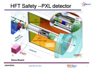
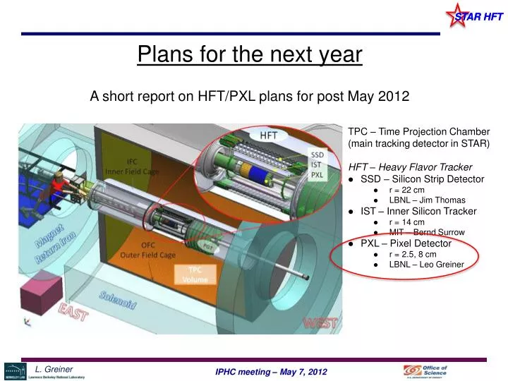
Plans for the next year A short report on HFT/PXL plans for post May 2012. TPC – Time Projection Chamber (main tracking detector in STAR) HFT – Heavy Flavor Tracker SSD – Silicon Strip Detector r = 22 cm LBNL – Jim Thomas IST – Inner Silicon Tracker r = 14 cm MIT – Bernd Surrow

E N D
Plans for the next year A short report on HFT/PXL plans for post May 2012 TPC – Time Projection Chamber (main tracking detector in STAR) HFT – Heavy Flavor Tracker • SSD – Silicon Strip Detector • r = 22 cm • LBNL – Jim Thomas • IST – Inner Silicon Tracker • r = 14 cm • MIT – Bernd Surrow • PXL – Pixel Detector • r = 2.5, 8 cm • LBNL – Leo Greiner
Outline • Existing HFT/PXL status and schedule • Testing Goals at IPHC • Immediate plans / discussion • Possible scenarios for the near term
Existing PXL status and schedule • CD-2/3 passed September 2011 – we are a fully funded DOE construction project. • Many thanks to IPHC group for years of collaboration, support and help including during reviews. • Significant management overhead, reports, reviews, etc. • The main task for 2012 is the construction and delivery of a three sector prototype detector by January of 2013.
Selected HFT Tasks for the next year • Installation of the new IDS pieces and new beam pipe in ~ July 2012. • Production of a prototype PXL detector using complete mechanics, installation tooling, sensors, RDO system, interface to STAR. This will allow for both an in beam test of the PXL design and a measurement of the charged particle environment at low radius. • The installation for the PXL prototype detector is scheduled for December 2012. • The SSD and IST detectors are not scheduled to be installed until summer 2013.
PXL tasks for 2012 • We have a deliverable of a working prototype detector (3 sectors) to be installed at the end of 2012. • Thus we need to produce first articles of all of the production stages for the final detector. • Tasks for 2012: • Production probe testing working for Ultimate sensors • Cable design complete with Cu conductors • New pre-production RDO (all boards) system working • Full firmware and software for data-taking • All mechanical designs complete and tested. • Mechanical structures fabricated. • Ladders => sectors fabricated + full scripted testing. • Metrology • Slow control system • Software for tracking using metrology data • Software for cosmic ray / beam testing tracking. • etc.
Steps to Prototype Detector Sensor and mechanical only. RDO, slow control, etc. not shown. Test ladder cable design Fix cable design (width) Fabricate cables Fix mechanical design Fabricate mech pieces Probe test sensors Prototype detector planned to be fabricated with Ultimate 1 sensors. Fabricate ladders Fabricate sectors Testing and metrology Deliver to STAR, test and install
Cable testing • Cable design validation is very relevant to many parts of the project; • The hybrid cable design itself is needed to fabricate ladders from a working design. • Mechanical – if additional cable width is needed we will need to re-design the mechanical parts including assembly fixturing. • Ultimate 2 submission – We wish to fully check the functioning of sensors on a ladder before submitting the next version of the sensors. A working hybrid cable design is required for most of the next production steps.
Next Steps • A design for the final cable has already been prepared assuming successful testing of the existing (one-power) design. • Perhaps this is an optimistic scenario • PCB shop at CERN will quote cost for initial design and wait to produce final cable design. • Produce PCBs • Additional testing and design steps will be discussed in MS’s talk.
Points to return to • Ultimate 2 submission schedule • Additional testing plans and schedule • Cable submission schedule
Aluminum conductor Ladder Flex Cable STAR PXL DETECTOR STRUCTURE PXL Sector 3 outer ladders 1 inner ladder STAR PXL Detector 10 sectors
Cable Structure Preliminary Design: Hybrid Copper / Aluminum conductor flex cable There are two cable regions joined by wire bonds Outer ladders have a simple rectangular driver region PCB. Inner ladders have a complex driver region PCB that incorporates a kapton flex region to allow the ladder interface connector to be routed to the top of the sector.
STAR PXL Ladder PCBs There are 3 PCBs to produce for the STAR PXL detector ladders. Low Mass Ladder PCB – common for all ladders Outer Ladder Driver PCB – joined to low mass PCB and used for outer ladders. Inner Ladder Driver PCB – joined to low mass PCB and used for inner ladders. There are 3 outer ladders for every 1 inner ladder.
Low mass ladder PCB All low mass ladder PCBs are the same design Prototypes will be copper conductor Production will be Aluminum conductor Board material: 25 µm kapton Conductor: 20 µm copper Solder mask: None Silk screen: None Final thickness: TBD – 150 µm? Finish: ENIG gold plate TOP STACKUP Kapton BOTTOM
Outer Ladder Driver PCB TOP STACKUP Board material: FR-4 Conductor: 1 oz. copper Solder mask: both sides Silk screen: TOP only Final thickness: 0.5 mm Finish: ENIG gold plate FR-4 BOTTOM PREPREG INNER 1 FR-4 INNER 2
Inner Ladder Driver PCB This is a composite PCB consisting of a kapton flex PCB with FR-4 PCB additions at each end. Connector End Driver End
Inner Ladder Driver PCB Kapton TOP/BOTTOM B A SECTION A-B SECTION A-B STACKUP Board material: TOP/Bottom – 25 µm kapton Conductor: 1 oz. copper Solder mask: both sides Silk screen: TOP only Final thickness: TBD – 150 um? Finish: ENIG gold plate TOP Kapton BOTTOM
Inner Ladder Driver PCB Connector End Board material: TOP/Bottom – kapton Inner1/Inner2 - FR-4 Conductor: 1 oz. copper Solder mask: both sides Silk screen: TOP only Final thickness: 0.5 mm Finish: ENIG gold plate TOP STACKUP Kapton BOTTOM PREPREG INNER 1 FR-4 INNER 2
Inner Ladder Driver PCB Driver End Board material: TOP/Bottom – kapton Inner1/Inner2 - FR-4 Conductor: 1 oz. copper Solder mask: both sides Silk screen: TOP only Final thickness: 0.5 mm Finish: ENIG gold plate TOP STACKUP Kapton BOTTOM PREPREG INNER 1 FR-4 INNER 2
Quantities: We would like to produce a prototype detector with ≥ 3 sectors. Yield arguments suggest that we will need: 40 Low Mass Ladder PCBs 35 Outer Ladder Driver PCBs 15 Inner Ladder Driver PCBs In addition, we would like to start the process of building ladders with Aluminum conductor PCBs so we would also like: 10 Low Mass Ladder PCBs with ~25 µm Aluminum conductor
Projected completion dates • Order Ultimate sensors: September 2011 • First Ladder cable in FR-4: Oct/Nov 2011 • First product probe testing: January 2012 • Ultimate probe testing complete: February 2012 • PXL RDO ready: April 2012 • First prototype sectors: August 2012 • Install Prototype detector: January 2013