Download
1 / 13
130 likes | 223 Vues
Learn about the main parts of a vehicle's heating system, including the heater core, blower, heater hoses, and heater valve. Explore different types of valves and control mechanisms. Discover the role of PTC heater elements and the transfer of heat to warm the air. Get insights into replacing heater cores and using quick-connect couplings for hose connections. Understand manual, vacuum, cable, and thermostatic control options. Explore control panels for front and rear climate control systems.

E N D
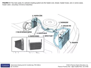
FIGURE 9-1 The main parts of a vehicle’s heating system are the heater core, blower, heater hoses, and, in some cases, heater valve. (Courtesy of Everco Industries)
FIGURE 9-2 Some heater systems use a valve (9) that can shut off the flow of hot coolant to the heater core (2). (Courtesy of Stant Manufacturing)
FIGURE 9-3 A heater control valve can be located at any of the positions shown.
FIGURE 9-4 This hybrid vehicle has a pump/bypass that can pump hot coolant through the heater core (b, bottom) when the engine is shut off. During engine operation, the bypass valve (b, top) allows normal circulation. (Courtesy of Toyota Motor Sales USA, Inc.)
FIGURE 9-5 The two PTC, positive temperature coefficient, heater elements help warm the heater core of this hybrid vehicle. (Courtesy of Toyota Motor Sales USA, Inc.)
FIGURE 9-6 Heat is transferred from the hot coolant flowing through the water tubes to warm the air flowing through the fins of the core.
FIGURE 9-7 The critical dimensions needed when replacing a heater core. (Courtesy of Four Seasons)
FIGURE 9-8 Two examples of the many shapes and sizes of heater cores. (Courtesy of Four Seasons)
FIGURE 9-9 Heater hose uses reinforced rubber construction (a) and is available in straight or molded (b) shapes. (Courtesy of Veyance Technologies, Inc.)
FIGURE 9-10 Some vehicles use quick-connect couplings for the heater hose connections. The hose is merely slid firmly onto the connector to make the connection. It should be disconnected carefully using a suitable tool. (Courtesy of Four Seasons)
FIGURE 9-11 A heater control valve can be operated manually (a), by vacuum control (b), through a mechanical cable (c), or by a thermostatic element (d). (a courtesy of Four Seasons; b, c, and d are courtesy of Stant Manufacturing)
FIGURE 9-12 The control panels for a vehicle with front and rear climate control systems. (Courtesy of Chrysler LLC)
FIGURE 9-13 This aftermarket heater assembly (a) contains a heater core (9) and blower (1–4). An exploded view is shown in (b). (Courtesy of Red Dot)