Download

1 / 41
410 likes | 449 Vues
This project details the challenges faced by Company X, offering a checklist to assess the current layout, employee feedback, a solution for a flexible shopfloor layout, and criteria for selecting part samples. The methodology includes modifications to the sequence analysis chart, robust layout designs, and a proposed layout for different parts. Benefits of the proposed layouts and contributions to industrial practice are also discussed.

E N D
Design of a Flexible Shopfloor Layout for a Fabrication Jobshop
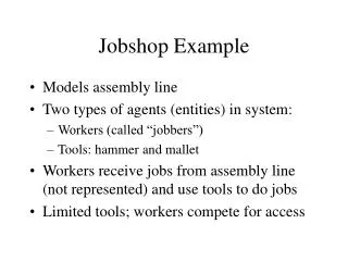
Details about Company X • Fabrication jobshop • Unstable part mix • Unstable production volumes • Variety of customers • Variety of materials
Concerns of Company X • High order throughput times • High WIP (Work-In-Progress) levels • Poor space utilization • Chaotic flows of material in current layout • Absence of aisles
Checklist to Assess the Current Layout • Evaluate existing facility • Identify core problems • Identify areas for improvements • Evaluate new layout to gauge improvements
Employee Feedback on Checklist • Availability of manufacturing equipment • “We are not flexible or efficient” • Inventories • “We are not running what we want to ship today” • Space utilization • “We have the opportunity to use our space better”
Solution Design of a flexible shopfloor layout • Robust layout • Changes in part mix • Changes in production volumes • Facilitate subsequent improvement strategies • Setup reduction • Scheduling
Input Data • Product routings • Sequence analysis chart • Layout drawing • Equipment inventory (Plant List)
Modifications to Sequence Analysis Chart • No BOM structure • Incorporated new processes, ex: HAA • Machine names not unique, ex: TA, BB • Converted TA to TA1, TA2, TA3 • Converted BB to BBa, BBb, BBc, etc. based on machine capabilities
Flexible Configuration for BB BBa = {5,9} BBc BBb = {5,9} BBd BBc = {3,4} BBd = {6,7} BBe = {BBf, BBa,b, BBd} BBf = {1, 2, BBc} { } = Primary Machines = In case of overload, orders get transferred to Secondary Machines
Methodology Samples From-To Chart RobustLayout BlockLayouts MigrationZones
Methodology Samples From-To Chart RobustLayout BlockLayouts MigrationZones
Criteria for Selecting Part Samples • Aggregate • The complete set • Customers • Top 3 in terms of volume • Lucent, ABB, (Ohaus and ITI) • Materials • Top 2 in terms of volume • CRS and AL
Start Input data file End of file Y A Stop N Read: Lot size & # of lots/year Flowchart for Computer Program Compute V=(lot size) * (# of lots/yr.) B
B Read: Machine Name Unique Machine Update Unique Machine List Y N Any more machines Y D C N A
C Read: Machine Name Unique Machine Y Update Unique Machine List Update From-To Chart with V D
Block Layouts • Symbolic representation of machines • Relative positions of machines in the shopfloor (7x4 grid)
Start Create Initial Random Solution All Possibilities Completed? Apply Pairwise Interchange Algorithm N Y Is the Solution Better? N Y Update Best Solution Is User Happy with the Best Solution? N Y Stop Report Best Solution
Migration Zones of Machines • Region of movement of a particular machine when layouts created for different samples are superimposed. • The smaller the migration zone the more robust the layout. 2 1 3 Migration Zone 4 5
Criteria for Evaluation of Layouts • Material handling cost • Space utilization • Aisle structure • Order throughput times • WIP Levels
Benefits of Proposed Layouts • Material Handling
Benefits of Proposed Layouts (contd) • Space reclaimed • New equipment, ex: Laser • New department, ex: Paint Booth • Visual (line-of-sight) scheduling • WIP reduction • Elimination of “junk” equipment
Contributions to Industrial Practice • Multi-sample approach to generating block layouts • Migration zones of machines • Automated generation of From-To chart • Integrated use of STORM and FactoryFlow for optimization support to user of FactoryFlow