The D0 DAQ and its Operational Control
300 likes | 446 Vues
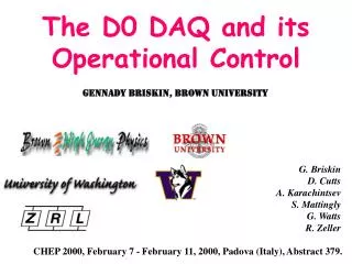
The D0 DAQ and its Operational Control. Gennady Briskin, Brown University. CHEP 2000, February 7 - February 11, 2000, Padova (Italy), Abstract 379. G. Briskin D. Cutts A. Karachintsev S. Mattingly G. Watts R. Zeller. The DØ Trigger System. Detector. Trigger . Full . Readout.

The D0 DAQ and its Operational Control
E N D
Presentation Transcript
The D0 DAQ and its Operational Control Gennady Briskin, Brown University CHEP 2000, February 7 - February 11, 2000, Padova (Italy), Abstract 379. G. Briskin D. Cutts A. Karachintsev S. Mattingly G. Watts R. Zeller
The DØ Trigger System Detector Trigger Full Readout Information DAQ ~7 MHz ~1 kHz Level 1 Level 3 ~10 kHz ~50-70 Hz Level 2 C/R ~1 kHz RIP Tape Output
Run II DAQ Numbers • Readout channels: • Will be ~800,000 in Run 2 • <250 kBytes>/event • Data rates: • 60-80 readout crates • Many to one: • All GS to one of 64 L3 farm nodes • Initial design capacity: • ~1000 Hz • 250 MBytes/sec into the DAQ/l3-farm • Staged upgrades to more than 3 GB/sec
New New New L3/DAQ Hardware Glossary Digitizing crate VBD VME Buffer/Driver VBD Readout Concentrator VRC { • Segment Bridge • Fibre Channel Interface • Event Tag Interface • Data Cable Interface FCI ETI DCI SB ETG Event Tag Generator MPM Multiport Memory Level-3 filter node
SB SB SB SB L3/DAQ Data Path data collection path VBD VBD VBD o o o VRC primary FC Path (1 of 8) VBD VBD VBD o o o L3 data distribution to Level 3 farm Levels 1,2 Levels 1,2 ETG trigger data trigger data MPM MPM o o o event tag event tag • direct flow from VBD to MPM • each data block flows freely and independently • blocks for different events flow simultaneously and asynchronously • recirculation loops allow maximum use of data path bandwidth • Segment Bridges use Event Tag data to perform complex realtime routing decisions path path MPM MPM o o o MPM MPM o o o MPM MPM o o o (stage C)
L3 Node (1 of 16) L3 Node (1 of 16) L3 Node (1 of 16) L3 Node (1 of 16) S (4 DATA CES L3 Node (1 of 16) L3 Node (1 of 16) ) Front End Token Readout Loop Front End Token Readout Loop Front End Crate Front End Crate Front End Crate Front End Crate VRC 1 VRC 8 Front End Crate Front End Crate Primary Fiber Channel Loop #8 Front End Crate Front End Crate Primary Fiber Channel Loop #1 SB 1 SB 4 Event Tag Loop Ethernet Ethernet ETG To Collector Router To Collector Router Trigger Framework Segment Data Cables Segment Data Cables ) )
DAQ Architecture • Data flow is unidirectional • No complex setup communication is required • Each packet is sent only once • No retransmission if packet error is detected • Routing is driven by the contents of the VBD header • No communication with front end crates • Sender does not know or care where data is going • Designed for expansion beyond the run 2 era
Front End Crate Digitizers Digitizers Digitizers VBD Token Control To next VBD or VRC Data Pathway 48 MBytes/sec From last VBD or VRC VME Buffer Driver Module • Digitized data enters DAQ system via a VBD module • Typically 4-6 Kbytes per VBD/event • Components: • VME interface with list processing DMA • Dual SRAM buffers • External data cable interface with token arbitration logic. • Performance: • VME: BLK mode DMA at 25-30 MB/sec • Data cable output: 48 MB/sec. • Token arbitration time: <10 usec.
FCI from last SB VBD 100 MB/s VBD Loop #1 Data Cable VRC VBD Token CLK VBD Token CLK Loop #2 Data Cable VBD 100 MB/s FCI to 1st SB VBD VBD Readout Concentrator • Bridges VBD readout loops to Primary Fibre Channel loop • Provides readout token generation and general front end loop management:e.g. initialization, resets, and diagnostics • Primary loop interface via full-duplex Fibre channel port • transmits data to first Segment Bridges (SB’s), receives recirculated packets from last SB;
VBD Readout Concentrator HD C A B L E Term & FB Trans 64/26 64/26 VRC 1 HD C A B L E HD C A B L E Term & FB Trans 64/26 PCI DP Mem 64/26 Buffer Mem i960 FC P O R T FC out FC in PCI/66 Pentium XXX 128Mb Ethernet HD C A B L E Term & FB Trans 64/26 64/26 PCI VRC 2 HD C A B L E HD C A B L E Term & FB Trans 64/26 DP Mem 64/26 Buffer Mem i960 FC P O R T FC out FC in
The Event Tag Generator • Receives L2 Accept Trigger Information • Correlates Trigger Framework information with preprogrammed parameters for Level-3 node configuration, and then classifies event as: • generic: any segment, any node; • targeted: specific segment/node; • special function: diagnostic, broadcast, etc. • Creates corresponding ‘event tag’ that instructs SB’s on how to handle data from that event. • Places event tag in primary tag queue and transmits it when tag queue is available. • Queue fill status is used to provide rate limiting feedback to Level 1 triggers • L1 disable lines
From Trigger FrameWork ET Creator (CAM Lookup) Monitor CPU Ethernet • 16 bit L3 Transfer Number • Trigger Bits ET Queue • Event Tag Format: • Header • Event Number • Flags (diagnostics or regular) • Segment Controller 1 Block • Event Type • FEC Readout Bit Masks • Segment Controller 2 Block • Event Type • FEC Readout Bit Masks • etc. Return ETG Monitor } L1 Disable } SC SC SC SC L3 Farm ETG System • Links L3/DAQ with the L1/L2 trigger systems • Uses trigger information for a given event to create an “event tag” which enables complex data block routing in real time
Segment Bridge • SB routes data from the VRCs to a L3 Node(s) • Bridge Primary Fibre Channel loop to Level-3 data cables • Each Level-3 Segment has a Segment Bridge • ETG circulates event tag information to each SB. • ETG/SB is capable of complex node assignments • Node assignment based on event type (calibration, etc…) • Shadow Nodes • A second nodes receives the same event; allows testing of new L3 exes • Allows partitioning into several simultaneous data taking runs • SBs are serially linked together • One can expand the number of farm segments
Event-Node Assignment Trigger-bit event type lookup tables ETG L2 Trigger Bits • Node Readies • Node-Event type lookup table SB Event Tag Event Type • Regular • CAL_CALIB • Regular + Shadow #2 • COSMIC Node Assignment
Segment Bridge • Receives Event Tag from ETG • accepts/declines the event based on characteristics of available L3 nodes
L3 Filter L3 Filter L3 Filter Process L3 Farm Nodes L3 Node Framework VME Crate Each 48 MB/s Control, Monitoring and Error Module MPM Node-VME I/O Module 100-BaseT Ethernet MPM DMA capable VME-PCI Bridge Shared Memory Buffers Collector Router Module L3 Filter Interface Module • Input rate starts at 1000 Hz • Output rate is ~50-70 Hz • Intel Based SMP System • Windows NT • As many L3 Filters as possible • Prototype hardware in hand Dedicated 100 Mbits/s Ethernet to Online Collector/Router
L3 Supervisor Interface L3 Filter Output Interface L3 Node FrameWork Control Pool Queue MPM Reader Event Buffer Shared Memory • Get a pointer to an event buffer • Configures MPMs for receiving new event • Wait till complete event arrives into MPM • Load event data into shared memory buffer • Insert event pointer into the next queue Data L3 Filter Input Interface Validation Queue L3 Filter Process Process Interface Event Validation • FECs presence validation • Checksum validation Filter Queue Process Interface Output Events Queue Output Pool Queue Command/Monitor/Error Shared Memory L3 Monitor Interface Collector/Router Network Interface L3 Error Interface • Determine where this event should be sent • Sent event to collector/router node Data to Online Host System
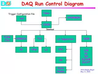
The L3 DAQ Control System Goals • High speed configuration changes • Run start/stop • Physics Run/Calibration Run Modes • Diagnose problems quickly
Environment • All nodes will use Commodity Hardware & Windows OS • C++ • MS Visual Studio 6.0 • Works well, IDE is a blessing. • Visual Source Safe for source control • Very tightly integrated into the MS Visual Studio IDE • Communication • ACE as the cross platform wrapper around TCP/IP stack • itc package to manage messages and event transport with D0 Online system (Fermi CD) • DCOM for internal control of DAQ components • XML message formatting for internal control/configuration of DAQ components
L3 Farm Node VRC VRC VRC VRC The Level 3 DAQ/Trigger system Collector Router Online System L3 Supervisor L3 Monitor SC SC SC SB ETG
DAQ Components States • Every DAQ component can be in 1 of the 6 states Start Run Boot Finish Run Idle Shut- down Pause Run
Auto Start System Auto Start Server Configuration (COM Object) Change Packages, Get Status, Reboot, etc. Configuration Database Package Database Web Server Client Machine Auto Start Service Get Package List Package Install Packages Running Packages
The Level 3 DAQ/Supervisor System • Translate D0 online system commands into L3 specific commands • Begin Run • End Run • Run Script ele_high on L2 Trigger bit 2 on 6 nodes of type REGULAR. • Report configuration errors (synchronous) • Must track a single online system command as it is distributed to DAQ components • Maintain DAQ System state
L3 Node L3 Node L3 Node L3 Node L3 Node L3 Supervisor Interface Supervisor Online System COOR Command Interface COOR Commands Configuration Request Direct Commands Current Configuration DB Resource Allocator Desired Configuration Data Base Command Generator Sequencer Commands
Any L3 Computer Any L3 Computer Process 1 Process 2 Process 3 Process 1 Process 2 Process 3 Shared Memory Shared Memory Shared Memory Shared Memory Shared Memory Shared Memory Transmitter Process Transmitter Process L3Monitor Collator Process Monitor Client Monitor Client Monitor Client Monitor System
Embedded Systems Embedded Systems Embedded Systems VBD Data Cables VRC Node 50 MB/s 50 MB/s VRC Programs 100 MB/s Control FCI to 1st SB 100 MB/s Disk L3 Monitor L3 Supervisor VRC Interface FCI from last SB DCOM DCOM
Trigger Framework ETG Node ETG Programs Embedded Systems Embedded Systems Embedded Systems Triggers Disable Triggers Control Disk L3 Monitor L3 Supervisor ETG Interface DCOM DCOM
Segment Bridge Interface FCI from VRC or SB 100 MB/s SB Node SB Programs FCI to next SB Embedded Systems Embedded Systems Embedded Systems 100 MB/s Control Disk MPM Data Cables DCOM DCOM L3 Monitor L3 Supervisor
Conclusion • Natural upgrade of the Run I DAQ • Allowed us to put together the framework for the L3 farm node with modest amounts of hardware effort • New DAQ hardware permits > 10 increase in bandwidth • DAQ control system is designed to be modular • makes use of industry standard software
The valiant warriors of D0 are strong thanks to a magic potion prepared by druid Getafix and this recipe is secret (all we know is that it has lobster and beer)