Hull – Superstructure Interaction
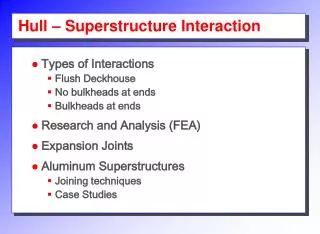
Hull – Superstructure Interaction. Types of Interactions Flush Deckhouse No bulkheads at ends Bulkheads at ends Research and Analysis (FEA) Expansion Joints Aluminum Superstructures Joining techniques Case Studies. Types of Interaction (House flush with side).

Hull – Superstructure Interaction
E N D
Presentation Transcript
Hull – Superstructure Interaction • Types of Interactions • Flush Deckhouse • No bulkheads at ends • Bulkheads at ends • Research and Analysis (FEA) • Expansion Joints • Aluminum Superstructures • Joining techniques • Case Studies
Types of Interaction (House flush with side) • The superstructure bends with the hull as one hull-girder • May consider contribution to longitudinal strength through Moment of Inertia
Types of Interaction (House not flush/no intermediate bulkheads) Stress Risers! • Deck beams are flexible; deckhouse acts independent of hull • Hogging and sagging puts large stresses on connection points • Best to terminate deckhouse with WT bulkhead (and/or longitudinal bulkhead or significant deck girders)
Modes of Interaction (House not flush, intermediate bulkheads) Full bulkhead maintains shape • Intermediate bulkhead forces superstructure to undergo same deflection as the hull • Between bulkheads the strain diminishes • Can cause large “lift off” forces at bottom of deckhouse (particularly the ends)– must be considered in design (fatigue analysis)
Design of Deckhouses • ABS Rules require that deckhouses with lengths greater than 10% of ship’s length located at midships have longitudinal members large enough to give a hull-girder section modulus in the deckhouse equal to that of the hull girder. • Usually design hull girder alone to withstand bending moments without the deckhouse • Method is sound but conservative
Research and Analysis • Non-linear stress distributions in deckhouse – Bleich • Shear and shear lag effects at deckhouse/hull – Schade • Full scale tests on SS President Wilson – Vasta • FEA (only area currently active)
Expansion Joints • Joints are cut in the superstructure above the main deck (strength deck). Bolted joints with slots sometimes used, or simply slit with waterproof cover. • Relieves deckhouse longitudinal bending stress so that it acts independent of hull. • Allows deckhouse to be designed for vertical loads and racking stresses. • Saves significant weight topside
HOUSE DECK Cover strip outside HOUSE DECK HOUSE SIDE SHELL PLATING STRENGTH DECK Flat bar face around circular cut at bottom of expansion joint Expansion Joints
Use of Expansion Joints • Must be spaced close enough to relieve deckhouse bending stresses • They introduce severe concentrations of stress at the bottom of the joints • Can lead to creaking and leaking in seaway if joining details not properly designed.
Aluminum in Deckhouses • Advantages • As strong as steel but Elastic Modulus 1/3 that of steel stresses are 1/3 of that in steel may eliminate need for expansion joints • Almost 2/3 reduction in weight over mild steel lowers weight of structure and KG improves stability • Disadvantages • Coefficient of thermal expansion almost double that of steel may cause distortions with temperature variations in service • Aluminum loses strength at elevated temperatures detrimental to damage control • Can lead to galvanic corrosion with steel • Difficult to join to steel structures (explosive or biweldable joints) • More expensive than mild steel • Potential brittleness of high strength aluminum
Aluminum Steel Joining Techniques • Rivets/Bolts • Explosion Bonding • Process uses an explosive detonation as the energy source to produce a metallurgical bond between metal components. One of the metals is accelerated by explosive detonation at a very high rate over a short distance resulting in a progressive collision of the materials. • The metals are forced together under several million psi pressure creating an electron-sharing bond that is typically stronger that the weaker of the parent metals. • Due to its use of explosive energy, the process occurs extremely fast; unlike conventional welding processes, parameters cannot be fine-tuned during the bonding operation. • The bonded product quality is assured through selection of proper process parameters: material surface preparation, plate separation distance prior to bonding, and explosive load, velocity, and detonation energy. • Biweldable strips (2002) Source: Clad Metal Division - Dynamic Materials Corp.
Aluminum in Naval Warships • U.S. Warships • Prior to DDG-51 most warships used aluminum in their superstructures for its various advantages • 1975: USS Belknap collided with USS John F. Kennedy and a major fire broke out on Belknap that melted most of its superstructure • 1991: USS Princeton detonated an Italian-made MRP acoustic mine under the ship’s quarterdeck. The blast detonated another mine three-hundred yards off the starboard beam. • A six-inch crack opened in the Princeton’s aluminum superstructure running up one side and down the other. More than 10% of the superstructure separated from the main deck.
USS Radford (DD 968) collision (1999) Split at bi-metallic joint in deck house frame 174