Download
1 / 12
120 likes | 250 Vues
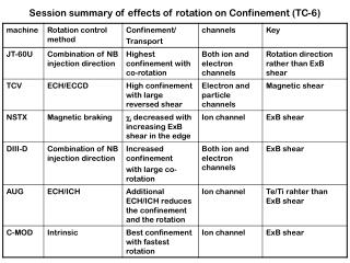
Effects of external non-axisymmetric perturbations on plasma rotation. L. Frassinetti, P.R. Brunsell, J.R. Drake, M.W.M. Khan, K.E.J. Olofsson Alfvén Laboratory, Royal Institute of Technology KTH Stockholm. Introduction. Braking of plasma rotation due to non-axisymmetric perturbations

E N D
Effects of external non-axisymmetric perturbations on plasma rotation L. Frassinetti,P.R. Brunsell,J.R. Drake, M.W.M. Khan, K.E.J. Olofsson Alfvén Laboratory, Royal Institute of Technology KTH Stockholm
Introduction Braking of plasma rotation due to non-axisymmetric perturbations - resonant perturbation RMP - non-resonant pert. non-RMP • EXTRAP T2R - The machine and the feedback (quick overview) - Diagnostics • Experimental results - Braking due to a RMP (1) helicity resonant close to the axis (2) helicity resonant far from the axis - Braking due to a non-RMP (3) internal non-resonant helicity n=-12 n=-15 OUTLINE n=-10
From: Y. Sun (FZJ) RMP RMP and Non-RMP INTRODUCTION RMPs are an essential tool for ELM mitigation in tokamaks Do they have only “positive” effects on the plasma? NO For example RMPs can produce: -density pump out -plasma braking Present understanding: the braking can be due to two phenomena (1) Localised electromagnetic torque -interaction between the static RMP and the corresponding TM • (2) Neoclassical toroidal viscosity torque • - Toroidal viscous force on plasma fluid as it flows • through a non- axisymmetric perturbation • - Collisions and particle drifts in non-axisymmetric field cause a • non-ambipolar radial particle flux (radial current) which gives a toroidal force.
EXTRAP T2R The device • EXTRAP T2R is a RFP with: • R=1.24m • a=0.18m • Ip ≈ 80-150kA • ne ≈ 1019m-3 • Te ≈ 200-400eV • tpulse≈ 20ms (no FeedBack) • tpulse≈ 90ms (with IS) shell The feedback by Olofsson E. • tshell≈13.8ms (nominal) • SENSOR COILS • 4 poloidal x 32 toroidal • sensor saddle coils (m=1 connected) • located inside the shell Active coils Sensor coils • ACTIVE COILS • 4 poloidal x 32 toroidal • active saddle coils (m=1 connected) • located outside the shell 0.6 0.4 0.2 0.0 m=1 n=-12 br1,n (mT) 0 20 40 60 Time (ms)
80 60 40 20 0 -20 80 60 40 20 0 -20 v1,n (km/s) v1,n (km/s) Poloidal velocity is not considered 0.0 0.2 0.4 0.6 0.8 1.0 -30 -25 -20 -15 -10 n r/a Plasma flow diagnostics 1.5 1.0 0.5 0.0 0.8 0.4 0.0 brightness 5-channel spectrometer for emissivity profile of impurities IOV (au) modelled experimental Spectrometer for Doppler shift of ion lines eOV (au) Reconstructed emissivity OV emissivity 80 60 40 20 0 OV velocity 0.0 0.2 0.4 0.6 0.8 1.0 r/a VOV (km/s) 80 60 40 20 0 -20 OV 0 10 20 30 40 50 60 OIV Time (ms) v1,n (km/s) OIII Plasma flow v(r): v(x,a,b,g) is assumed Free parameters from minimization of modelled and experimental vi OII Modelled vi Experimental vi 0.0 0.2 0.4 0.6 0.8 1.0 r/a [Cecconello, PPCF 2006] Magnetic diagnostics bq 4 poloidal x 64 toroidal local sensors (m=1 connected) located inside the shell.
(1,-12) most internal TM (1,-12) p 0 -p flow profile (spectroscopy) 80 60 40 20 0 -20 (1,-12) before RMP during RMP Phase (1,-19) flow (km/s) 20.0 20.05 20.10 20.15 20.20 Time (ms) p 0 -p 0.0 0.2 0.4 0.6 0.8 1.0 r/a velocity profile (magnetics) Phase (1,-19) 80 60 40 20 0 -20 before RMP during RMP 40.0 40.05 40.10 40.15 40.20 vmag (km/s) Time (ms) 0.0 0.2 0.4 0.6 0.8 1.0 r/a BRAKING DUE TO A RMP 120 100 80 60 40 20 0 0.10 0.08 0.06 0.04 0.02 0.00 -0.02 Ip ()kA q(r) 1.0 0.8 0.6 0.4 0.2 0.0 0.0 0.2 0.4 0.6 0.8 1.0 r/a br1,n (mT) Flow braking 80 60 40 20 0 vOV (km/s) 80 60 40 20 0 Braking occurs for all TMs v1,-12 (km/s) 0 20 40 60 Time (ms)
Average during RMP (each dot corresponds a different shot) 60 40 20 0 4ms RMP 0.6mT The flow seems to brake with a lower rate V (km/s) 0.0 0.2 0.4 0.6 0.8 1.0 brRMP (mT) velocity profile (magnetics) 80 60 40 20 0 -20 before RMP during RMP vmag (km/s) (1,-12) 0.0 0.2 0.4 0.6 0.8 1.0 r/a BRAKING vs RMP amplitude 80 60 40 20 0 10ms RMP 0.4mT vOV (km/s) 80 60 40 20 0 v1,-12 (km/s) 0 20 40 60 Time (ms) RMP 0.4 mT braking in 10ms to v~30km/s RMP 0.6 mT braking in 4ms to v~10km/s (1,-12) is locked to the wall (RMP) but the other TMs still rotate!
BRAKING DUE TO A RMP FAR FROM THE AXIS (1,-15) (1,-15) velocity profile (magnetics) velocity profile (magnetics) 80 60 40 20 0 -20 RMP (1,-12) RMP (1,-15) before RMP during RMP vmag (km/s) before RMP during RMP 0.0 0.2 0.4 0.6 0.8 0.0 0.2 0.4 0.6 0.8 r/a r/a 10 0 -10 -20 -30 region of max Dv Dvmag (km/s) 0.0 0.2 0.4 0.6 0.8 0.0 0.2 0.4 0.6 0.8 r/a r/a (1,-15) resonant at r/a~0.4 0.10 0.08 0.06 0.04 0.02 0.00 -0.02 120 100 80 60 40 20 0 Any difference between -12 and -15? YES q(r) Ip ()kA 0.0 0.2 0.4 0.6 0.8 1.0 1.0 0.8 0.6 0.4 0.2 0.0 r/a br1,n (mT) 80 60 40 20 0 vOV (km/s) 80 60 40 20 0 v1,-12 (km/s) 0 10 20 30 40 50 60 Time (ms)
BRAKING DUE TO A RMP FAR FROM THE AXIS 80 60 40 20 0 -20 before RMP during RMP vmag (km/s) (1,-15) 0.0 0.2 0.4 0.6 0.8 1.0 r/a velocity profile (magnetics) 80 60 40 20 0 -20 before RMP during RMP vmag (km/s) (1,-12) 0.0 0.2 0.4 0.6 0.8 1.0 r/a Comparison of braking due to RMP (1,-15) and RMP (1,-12) Average during RMP (each dot corresponds a different shot) 60 40 20 0 Vmag (km/s) 0.0 0.2 0.4 0.6 0.8 1.0 1.2 brRMP (mT)
velocity profile (magnetics) velocity profile (magnetics) 80 60 40 20 0 -20 80 60 40 20 0 -20 RMP (1,-12) non-RMP (1,-10) vmag (km/s) 0.0 0.2 0.4 0.6 0.8 0.0 0.2 0.4 0.6 0.8 r/a r/a 10 0 -10 -20 -30 -40 -50 10 0 -10 -20 -30 Dvmag (km/s) 0.0 0.2 0.4 0.6 0.8 0.0 0.2 0.4 0.6 0.8 r/a r/a BRAKING DUE TO A non-RMP (1,-10) non-resonant 0.10 0.08 0.06 0.04 0.02 0.00 -0.02 120 100 80 60 40 20 0 q(r) Ip ()kA 0.0 0.2 0.4 0.6 0.8 1.0 r/a 1.0 0.8 0.6 0.4 0.2 0.0 (1,-10) br1,n (mT) 80 60 40 20 0 vOV (km/s) Not a significant difference 80 60 40 20 0 v1,-12 (km/s) 0 10 20 30 40 50 60 Time (ms)
Average during RMP (each dot corresponds a different shot) RMP (1,-12) non-RMP (1,-10) 60 40 20 0 V (km/s) In this region the RMP is very perturbative 0.0 0.2 0.4 0.6 0.8 0.0 0.2 0.4 0.6 0.8 brRMP (mT) brRMP (mT) 80 60 40 20 0 -20 (1,-12) before RMP during RMP (1,-12) vmag (km/s) 0.0 0.2 0.4 0.6 0.8 1.0 0.0 0.2 0.4 0.6 0.8 1.0 r/a r/a BRAKING vs non-RMP amplitude 0.8 0.6 0.4 0.2 0.0 br1,n (mT) 60 40 20 0 vOV (km/s) 60 40 20 0 V1,-12 (km/s) 0 10 20 30 40 50 60 Time (ms) Not a significant differences so far
CONCLUSIONS MAIN CONCLUSION: clear evidence of plasma rotation braking due to external perturbations