Download
1 / 13
130 likes | 280 Vues
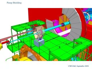
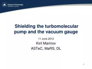
Shielding the turbomolecular pump and the vacuum gauge. 11 June 2013 Kiril Marinov ASTeC, MaRS, DL. Design considerations. The external field is of the order of 40 mT. The pump can tolerate 5 mT, regardless of the field direction.

E N D
Shielding the turbomolecular pump and the vacuum gauge 11 June 2013 Kiril Marinov ASTeC, MaRS, DL
Design considerations The external field is of the order of 40 mT. The pump can tolerate 5 mT, regardless of the field direction. The proposed solution is a 15 mm thick AISI 1010 box, 600X170X170 mm. It “works” (kind of) but is quite heavy ~57 kg. Since the valve does not and will not need shielding in the future is it possible to make the pump shield smaller, thinner and lighter ~8 kg External field parallel to the long side of the shield is the worst case scenario, as shown earlier. This configuration required 15 mm thick walls for the larger shield Reducing the shielded volume reduces the wall thickness. Halving the shield height has a big impact on performance. I do not have exact drawings of the components that need to be shielded. Have some LD photos and sketches instead. As discussed with Craig dimensions will be finalized when/if the shields are engineered.
Concept New Old Φ60 Φ110 170 300 Binmax<<<B0 15 mm thick AISI 1010 steel 10 mm thick AISI 1010 steel 600 ~8 kg ~57 kg
Installation Not to scale The two halves can be held together by steel bands. The gap can be controlled by a thin gauge during assembly, should not be much bigger than 0.1 mm.
Installation Φ80 mm flanges Shielded area Φ90 mm inner diameter
External field generation External field generated by a window-frame magnet Using the built-in option in opera B B
External field generation method When the external field is generated by an external magnet the execution is faster and takes fewer iterations. Field gradient can be added, if needed. When the built-in option in Opera is used one does not need to re-mesh the model after the field direction has been changed. Not sure what boundary conditions are implemented for the external field, as in the general case it is neither normal nor tangential to the boundary.
Performance The field inside the shielded area is below the 5 mT limit. The 220 mm “safe” area can be extended further by 3-4 cm by a adding a single chimney. The external field is axial. The external field is radial B B 220
Performance II “Hedgehog” plot of H B The external field is axial. Field out Peak flux density in the wall Radial field is present Field in
The vacuum gauge shield Φ50 Φ110 Φ70 200 150 10 mm thick AISI 1010 steel ~6 kg 50 The same cylinder as used for the pump, only 200 mm long
Performance The field inside the shielded area is below 5 mT. The acceptable limit is 10 mT. The 140 mm “safe” area is more than sufficient as the gauge itself is ~100 mm long. The external field is radial The external field is axial. B B 140
Performance When the external field is at 45o the result is very similar to that obtained with axial field. The safe zone extends by less than 1 cm. When the external field is at 10o w.r.t. the X-axis the result is similar to the radial field case. The external field is at 45o The external field is at 10o with respect to the X-axis. B B
Summary • Pump shield has been improved substantially. The target 5 mT field can now be reached safely regardless of the external field direction. The shield is now ~8 kg (not ~60 kg, as before). Wall thickness has been reduced from 15 mm to 10 mm. • Shielding solution for the vacuum gauge has been found as well. The target field in the shielded area is easy to achieve. • 75% of the work on the cryostat shielding (PSU, pump and vacuum gauge) is now complete. Need to look at magnetic forces, as promised. The “refrigerator” (cold head) shield still remains to be completed. • I will take some time off the MICE shielding work in order to concentrate on preparations for MT23 in July.