Download
1 / 124
1.25k likes | 1.49k Vues
Chapter 8: Troubleshooting Converged Networks. CCNP TSHOOT: Maintaining and Troubleshooting IP Networks. Chapter 8 Objectives. Troubleshoot Wireless issues in a converged network supporting wireless devices and clients.

E N D
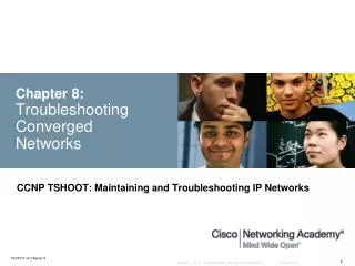
Chapter 8:Troubleshooting Converged Networks CCNP TSHOOT: Maintaining and Troubleshooting IP Networks
Chapter 8 Objectives • Troubleshoot Wireless issues in a converged network supporting wireless devices and clients. • Troubleshoot network issues in a converged network supporting Unified Communications. • Troubleshoot network issues in a converged network supporting video.
Section Overview • The focus of this section is on the readiness of the wired network to support wireless deployments and the impact of wireless traffic and services on the rest of the network. • This includes network services such as: • Power over Ethernet (PoE) • Dynamic Host Configuration Protocol (DHCP) • Quality of service (QoS) • Security • The Cisco Unified Wireless Network is composed of five interconnected element: • Client devices • Access points • Network unification • World-class network management • Mobility services
Common Wireless Integration Issues • Designing (and troubleshooting) a wireless network that integrates into a campus network requires several factors to be considered: • Is the wireless network based on the autonomous model or will it be based on its counterpart, the split MAC model (using lightweight access points and wireless controllers)? • What are the switch capabilities and requirements in terms of PoE, trunking, wireless local-area network (WLAN)-to-VLAN mapping, security, and QoS? • How will the Lightweight Access Point Protocol (LWAPP) be handled? • What type of roaming will the network support?
Standalone Wireless Solution • Autonomous access points (APs) provide all the wireless services. • Deployment is based on those APs functioning as critical wireless devices. • Other network devices provide services such as PoE, security and QoS. • Network servers, such as the Cisco Secure Access Control Server (ACS), are used for security and implement protocols such as RADIUS and TACACS+.
Split MAC or Lightweight Solution • The controller-based architecture splits the processing of the IEEE 802.11 protocol between two devices: The AP and a centralized Cisco wireless LAN controller (WLC). • The processing of the 802.11 data and management protocols and the AP functionality is also divided between the two devices. • This approach is called split MAC or lightweight. • Communications between the devices (lightweight APs and the WLCs) are implemented through LWAPP tunnels.
Wireless Integration Issues – Cont. • The model used defines where and how to troubleshoot potential problems when integrating the wireless infrastructure into a campus LAN. • The location of power source equipment, the configuration of trunks, and the mapping between WLANs and VLANs are important in gathering information for troubleshooting. • The wireless security solution is important in the proper transport of protocols such as LWAPP across the wired network. • Firewalls and access control lists (ACLs) must allow the protocol between APs and Cisco WLCs.
Wireless Integration Issues – Cont. Some common wireless integration issues include: • Traffic flow from client to WAP - Even if there is radio frequency (RF) connectivity between the AP and the client, there can still be a problem at the side where traffic flows from the client, through the AP, to the rest of the network. • WLC issues - In a controller-based solution, the boundary between the wireless and the wired network is the Cisco WLC because traffic is tunneled between the AP and the WLC. • Filtering issues - If any filters are configured on either the Ethernet side or the radio side of the AP, disable them temporarily, until you resolve connectivity issues. • IP addressing issues – IP addressing typically needs to be investigated, especially in roaming scenarios. • QoS issues - Maintaining QoS markings consistently across wireless-to-wired boundaries is important. • Other potential issues – Can be related to the network services typically provided by the switches that are connected to APs (such as POE).
Wireless Integration Issue Tools • Use an appropriate troubleshooting approach (top-down, bottom-up, divide-and-conquer, etc.). • Use your knowledge of switching during information gathering. Issues may be related to trunking, VLANs, and switch port configuration. • Use a design tool such as the Cisco Power Calculator for POE issues. • Useful wireless troubleshooting commands: • show vlan • show interfaces status • show interfaces trunk • show interfaces switchport • show access-lists • show cdpneighbors
WLAN Connectivity Troubleshooting Example 1: Misconfigured Trunk
WLAN Troubleshooting Example 1 – Cont. • Wireless service has stopped and clients are not able to associate to the AP. • From the wired PCs used for troubleshooting, it is not possible to connect to the AP or the WLC, using either Secure Shell (SSH) or HTTP-Secure (HTTPS). • Use a bottom-up approach and start with the access switch • Use the show cdp neighbors command to toidentify which ports are connected to the controller and access point. • Based on the results shown the WLC connects to interface Gi0/36 and the AP connects to interface Gi0/37. SW1# show cdp neighbors Capability Codes: R - Router, T - Trans Bridge, B - Source Route Bridge S - Switch, H - Host, I - IGMP, r - Repeater, P - Phone Device ID Local Intrfce Holdtme Capability Platform Port ID ap Gig 0/37 128 T I AIR-LAP125 Gig 0 521-8 Gig 0/39 135 AIR-LAP521 Fas 0 521-7 Gig 0/34 122 AIR-LAP521 Fas 0 Cisco_9a:8c:e0 Gig 0/36 175 H AIR-WLC210 Unit - 0 Slot – 0 Port - 1
WLAN Troubleshooting Example 1 – Cont. • Next, examine the status of the interfaces with the show interface statuscommand. • The Gi0/37 interface connected to the AP is associated to VLAN 10, and the Gi0/36 interface connected to the WLC is configured as trunk. SW1# show interface status Port Name Status vlan Duplex Speed Type Gi0/1 notconnect 1 auto auto 10/100/1000BaseTX Gi0/2 notconnect 1 auto auto 10/100/1000BaseTX <output omitted> Gi0/34 connected 1 a-full a-100 10/100/1000BaseTX Gi0/35 notconnect 1 auto auto 10/100/1000BaseTX Gi0/36 connected trunk a-full a-100 10/100/1000BaseTX Gi0/37 connected 10 a-full a-1000 10/100/1000BaseTX Gi0/38 notconnect 1 auto auto 10/100/1000BaseTX Gi0/39 connected 1 a-full a-100 10/100/1000BaseTX <output omitted>
WLAN Troubleshooting Example 1 – Cont. • Find out which VLANs are used for AP to WLC communication, which VLAN is used for client traffic, and whether the access point is operational and registering to the WLC using LWAPP or Control and Provisioning of Wireless Access Points (CAPWAP). • The AP has a static IP address and the WLC and the AP should be on the same VLAN, but the WLC is not seeing registration requests from the AP. • The static IP address on the AP rules out DHCP preventing the AP from initiating an LWAPP request. • The Layer 1 and Layer 2 status of the interfaces are operational for both the wired and wireless side, for both the AP and the WLC.
WLAN Troubleshooting Example 1 – Cont. • If the AP cannot register with the WLC, it will not be able to service client requests. • The AP’s request originates from interface Gi0/37, which is associated to VLAN 10, and must traverse the trunk link associated with Gi0/36 to reach the WLC. • Verify that VLAN 10 is allowed on the trunk interface (Gi 0/36), using the show interfaces switchportcommand. • The output shown reveals that only VLAN 1 is enabled (allowed) on the trunk. • Other VLANs such as VLAN 10 are not allowed on the trunk. SW1# show interfaces switchport | begin 0/36 Name: Gi0/36 Switchport: Enabled Administrative Mode: trunk Operational Mode: trunk Administrative Trunking Encapsulation: dot1q Operational Trunking Encapsulation: dot1q Negotiation of Trunking: On Access Mode VLAN: 1 (default) <output omitted> Trunking VLANs Enabled: 1 Pruning VLANs Enabled: 2-1001 Capture Mode Disabled <output omitted>
WLAN Troubleshooting Example 1 – Cont. • The wireless team tells you that the client VLAN is 10, and that the management VLAN is 20. • Add the appropriate VLANs to the list of allowed VLANs on the trunk interface to correct the problem. • Use the switchport trunk allowed vlan add 10,20command so that VLANs 10 and 20 are allowed on the trunk interface Gi 0/36. SW1# conf t Enter configuration commands, one per line. End with CNTL/Z. SW1(config)# interface g0/36 SW1(config-if)# switchport trunk allowed vlan add 10,20 SW1(config-if)# end SW1#
WLAN Connectivity Troubleshooting Example 2: Duplex and Trust Issues
WLAN Troubleshooting Example 2 – Cont. • The wireless operations team complains about the reliability and performance of wireless traffic. • The symptom they observe is that the AP interface pointing to the wired network goes up and down intermittently, and when the port is operational, there is a substantial slowdown on Voice over WLAN. • First, display the log and look for clues about the interface (Gi 0/34) that apparently goes up and down intermittently. • Next, use the show logging | include 0/34 command on SW1, which indicates a duplex mismatch problem. SW1# show logging | include 0/34 00:12:00: %CDP-4-DUPLEX_MISMATCH: duplex mismatch discovered on GigabitEthernet0/34 (not half duplex), with 521-7 FastEthernet0 (half duplex) 00:13:00: %CDP-4-DUPLEX_MISMATCH: duplex mismatch discovered on GigabitEthernet0/34 (not half duplex), with 521-7 FastEthernet0 (half duplex) 00:14:00: %CDP-4-DUPLEX_MISMATCH: duplex mismatch discovered on GigabitEthernet0/34 (not half duplex), with 521-7 FastEthernet0 (half duplex) 00:15:00: %CDP-4-DUPLEX_MISMATCH: duplex mismatch discovered on GigabitEthernet0/34 (not half duplex), with 521-7 FastEthernet0 (half duplex) <output omitted>
WLAN Troubleshooting Example 2 – Cont. • There is a duplex mismatch, but you should see the duplex mismatch messages on the console, too. • The show logging command on SW1 indicates that console logging is disabled, which makes sense for a production switch. • If you enable it, you will see the duplex mismatch messages. • Fix the duplex problem by configuring the interface for full-duplex 100 Mbps. • Note that it is a good practice to find out why the interface was set to half duplex to begin with. SW1# show logging Syslog logging: enabled (0 messages dropped, 1 messages rate-limited, 0 flushes, 0 overruns, xml disabled, filtering disabled Console logging: disabled <output omitted> SW1# conf t Enter configuration commands, one per line. End with CNTL/Z. SW1(config)# int g0/34 SW1(config-if)# duplex full SW1(config-if)# speed 100 SW1(config-if)# end
WLAN Troubleshooting Example 2 – Cont. • After fixing the SW1 Gi0/34 duplex problem, the wireless team informs you that the AP comes up and does not go down again • They are still experiencing performance issues, especially for VoIP traffic coming from the wireless network. • Use the show processes cpu command to determine if high CPU utilization is an issue • The output shows a relatively low level of utilization at this point and not too far off baseline for this device. SW1# show processes CPU CPU utilization for five seconds: 4%/0%; one minute: 6%, five minutes: 5% PID Runtime(ms) Invoked uSecs 5Sec 1Min 5Min TTY Process 1 0 5 0 0.00% 0.00% 0.00% 0 Chunk Manager 2 0 275 0 0.00% 0.00% 0.00% 0 Load Meter 3 0 33 0 0.00% 0.00% 0.00% 0 SpanTree Helper 4 1019 149 6838 0.00% 0.07% 0.05% 0 Check heaps 5 0 1 0 0.00% 0.00% 0.00% 0 Pool Manager 6 0 2 0 0.00% 0.00% 0.00% 0 Timers 7 118 845 139 0.00% 0.00% 0.00% 0 ARP Input 8 0 1 0 0.00% 0.00% 0.00% 0 AAA_SERVER_DEADT 9 0 2 0 0.00% 0.00% 0.00% 0 AAA high-capacit <output omitted>
WLAN Troubleshooting Example 2 – Cont. • Wireless voice traffic may not be properly prioritized when entering the network. • Possibly, the voice traffic may not be tagged with proper QoS priorities. • With LWAPP deployment, the AP uses the differentiated services code point (DSCP) field to tag packets. • Check to see whether the switch port is honoring that using the show mls qos int gi0/34command to display the trust boundary settings. • The output indicates that the switch does not trust anything coming from the AP. SW1# show mls qos int g0/34 GigabitEthernet0/34 trust state: not trusted trust mode: not trusted trust enabled flag: ena COS override: dis default COS: 0 DSCP Mutation Map: Default DSCP Mutation Map Trust device: None qos mode: port-based
WLAN Troubleshooting Example 2 – Cont. • Set the switch port (Gi0/34) to trust DSCP values using the mls qos trust dscp command. • The output of the show mls qos command now indicates that the switch is trusting DSCP values. • The wireless network support staff confirm that performance issues are alleviated for VoWLAN traffic. SW1(config)# int g0/34 SW1(config-if)# mlsqos trust dscp SW1(config-if)# end SW1# SW1# show mlsqosint g0/34 GigabitEthernet0/34 trust state: trust dscp trust mode: trust dscp trust enabled flag: ena COS override: dis default COS: 0 DSCP Mutation Map: Default DSCP Mutation Map Trust device: None qos mode: port-based
WLAN Connectivity Troubleshooting Example 3: LWAPP Denied by New Security
WLAN Troubleshooting Example 3 - Cont. • The wireless team tells you that wireless operations have stopped and that none of the APs are able to register to the WLC. • Based on a recent change in security policy, you find that Cisco IOS firewall services were installed in router R1. • Router R1 is performing inter-VLAN routing and the reported symptom points to the possibility of LWAPP traffic being denied by the firewall. • Cisco IOS Software allows the firewall to be configured using one of two methods: • The classical Cisco IOS firewall • The zone-based policy firewall
WLAN Troubleshooting Example 3 – Cont. • A check of the zone-based policy using the show zone-pair securitycommand produces an error message indicating there are no zone-based policies configured on this router. • Next, check for interface ACLs on the router using the show ip interfacecommand for the R1 interface pointing to the AP side of the connection. • This reveals an ACL called FIREWALL applied inbound to the R1 interface Fa0/0. R1# show ip interface Fa0/0 FastEthernet0/0 is up, line protocol is up Inbound access list is FIREWALL <output omitted>
WLAN Troubleshooting Example 3 – Cont. • Display access lists on R1 using the show access-list command. The FIREWALL ACL allows routing protocols and management protocols such as SSH. • The LWAPP ports, AP-to-WLC control messages (UDP 12223) and user traffic (UDP port 12222) through the LWAPP tunnel are not permitted by the firewall. • Designers of the security policy must be aware of the services and applications running on the network. R1# show access-list Extended IP access list 100 10 permit udp 10.10.10.0 0.0.0.255 any eq 12223 20 permit udp any anyeq 12223 Extended IP access list FIREWALL 10 permit icmp any any echo-reply 20 permit tcp any anyeq www 30 permit tcp any anyeq ftp 40 permit tcp any anyeq ftp-data 50 permit tcp any anyeq telnet 60 permit tcp any anyeqsmtp 70 permit tcp any anyeq pop3 80 permit eigrp any any 90 permit udp any anyeq rip
WLAN Troubleshooting Example 3 – Cont. • Add a line to the ACL, and a remark indicating why this line was added. • Permit UDP 12222 for user data traffic, and UDP 12223 for AP-to-WLC control messages. • The wireless team reports that this fix seems to have solved the problem. • Monitor the accuracy of the change and the potential implications it might have. • The show access-listscommand can displa the number of packets matching each ACL line. R1# conf t Enter configuration commands, one per line. End with CNTL/Z. R1(config)# ip access-list extended FIREWALL R1(config-ext-nacl)# remark ---allowing LWAPP control and data ports--- R1(config-ext-nacl)# permit udp any any range 12222 12223 R1(config-ext-nacl)# end
WLAN Troubleshooting Example 4 - Cont. • The AP and the WLC are in different VLANs. • Router R1 is performing inter-VLAN routing and also acts as the DHCP server for the APs. • The wireless team states that none of the APs can register to the WLC. • All APs are DHCP clients but are not able to obtain their IP address from the DHCP server (which is R1 at address 10.50.50.100). • APs must first obtain an IP address lease from the DHCP server. • After the APs have obtained an IP address, they can register with the WLC.
WLAN Troubleshooting Example 4 – Cont. The show ip dhcp server statistics command shows some statistics but no conclusions can be drawn. Clear the statistics using the clear ip dhcp server statistics command and reissue the show command, which shows no activity this time. R1# clear ip dhcp server statistics R1# R1# show ip dhcp server statistics Memory usage 5317 Address pools 1 Database agents 0 Automatic bindings 2 Manual bindings 0 Expired bindings 0 Malformed messages 0 Message Received BOOTREQUEST 0 DHCPDISCOVER 0 DHCPREQUEST 0 DHCPDECLINE 0 DHCPRELEASE 0 DHCPINFORM 0 Message Sent BOOTREPLY 0 DHCPOFFER 0 DHCPPACK 0 DHCPNAK 0
WLAN Troubleshooting Example 4 - Cont. • The debug ip udp command shows no reference to UDP port 67 (DHCP client). • The DHCP clients (APs) are in a different subnet than the DHCP server so this could be a DHCP relay agent problem. • Use the show run interface gi0/34 command for the port that points to the APs, but there is no ip-helper address command. • This switchport is associated to VLAN 10, so inspect interface VLAN 10 instead. There is no IP Helper-address configured there either. SW1# show running-config interface g0/34 Building configuration... Current configuration : 108 bytes ! interface GigabitEthernet0/34 switchport access vlan 10 switchport mode access mlsqos trust dscp end SW1# show running-config interface vlan 10 Building configuration... Current configuration : 61 bytes ! interface vlan10 ip address 10.10.10.1 255.255.255.0 end
WLAN Troubleshooting Example 4 - Cont. • The show running | include helpercommand reveals that one IP helper address is configured on the switch • It is pointing to an old DHCP server address and it is not on the right interface. • On interface VLAN 10 enter the correct IP helper address. • The debug results now show UDP packets arriving at the DHCP server (R1). SW1# show running-config | include helper ip helper-address 10.100.100.100 SW1# SW1# conf t Enter configuration commands, one per line. End with CNTL/Z. SW1(config)# intvlan 10 SW1(config-if)# ip helper-address 10.50.50.100 SW1(config-if)# end SW1# R1# 02:13:57: UDP: rcvd src=0.0.0.0(68), dst=255.255.255.255(67), length=584 02:13:58: DHCPD: assigned IP address 10.10.10.115 to client 0100.1bd5.1324.42. 02:13:58: UDP: sent src=0.0.0.0(67), dst=255.255.255.255(68), length=308 02:13:58: UDP: sent src=0.0.0.0(67), dst=255.255.255.255(68), length=308 02:13:58: UDP: rcvd src=0.0.0.0(68), dst=255.255.255.255(67), length=584
WLAN Troubleshooting Example 4 - Cont. • The wireless support team verifies the successful AP IP address assignment; however, there is still no registration into the WLC. • The wireless operations team tells you to check the configuration of option 43 on the DHCP server. • On the DHCP server, you display the details of the address pool using the show ip dhcp pool command and there is no option 43 configured. R1# show running-config | section ip dhcp pool ip dhcp pool vlan10 network 10.10.10.0 255.255.255.0 default-router 10.10.10.1
WLAN Troubleshooting Example 4 - Cont. • Option 43 is used to inform the DHCP client of the WLC AP-management IP address. • Use the ip dhcp poolcommand for VLAN 10 and enter the AP-management IP address as part of option 43. • The command format is option 43, followed by the correct IP address in hexadecimal format, as shown in the example. • If there is only one WLC management address, the Length is 04 (hex), and in this case the WLC management IP address is 10.10.10.10, which is 0a0a0a0a (hex). R1# conf t Enter configuration commands, one per line. End with CNTL/Z. R1(config)# ip dhcp pool vlan10 R1(dhcp-config)# option 43 hex f1040a0a0a0a R1(dhcp-config)# end R1#
Troubleshooting Unified Communications Issues in a Converged Network
Section Overview • The focus of this section is convergence, an integral part of most networks. • It deals with the readiness of a campus network to support converged services, such as unified communications or IP telephony. • IP telephony services provided over the campus infrastructure require the coexistence of data and voice. • Types of traffic are differentiated and delay-sensitive voice traffic is prioritized using QoS policies to mark and qualify traffic as it traverses the campus switch blocks. • VLANs keep voice traffic separate from other data. • The underlying routing and switching infrastructure must providing a reliable, efficient, and secure transport for signaling traffic and the gateway traffic to forward calls to the PSTN or WAN destinations.
Unified Communications Integration Issues The converged network shows the main elements such as voice gateway, CUCM, Cisco Unity (for voice mail), telephony endpoints (IP phones, conference units), LAN router and switches, WAN, and PSTN.
Unified Communications Design • The following list summarizes the design considerations of integrating unified communications into a campus network. • These can involve multiple components of the network, multiple layers of the OSI model, multiple integrated technologies and potentially, multiple operations and support teams within an organization. • Quality of service: Bandwidth, delay, jitter, packet loss, network QoS readiness, trust boundaries, switch QoS • High availability: STP/RSTP, HSRP/GLBP/VRRP • Security: Traffic segregation (voice versus data VLANs), firewalling/filtering • Provisioning and management: PoE, DHCP, TFTP, NTP, CDP, trunking, VLANs
Unified Communications Components In addition to QoS and VLAN management issues, the Unified Communications network requires specific components that might become additional sources of problems. These are services that use the underlying VLAN and switching infrastructure: • Power (PoE) must be readily available to endpoints. • Repositories of firmware and configuration files through TFTP • Time synchronization (Network Time Protocol [NTP]) for cryptographic authentication • Cisco Discovery Protocol (CDP) to facilitate the IP phone booting process • DHCP must be accessible to provide IP information for the phone
Unified Communications – IP Phones • Support engineers need to be familiar with the IP phone boot process. • Several devices, services, and protocols need to work in harmony for the successful initialization and startup of the IP phone.
IP Phone Boot Process The following is the IP phone boot process : • Step 1. The IP phone powers on. • Step 2. The phone performs a power-on self-test, or POST. • Step 3. The phone boots. • Step 4. The phone uses CDP to learn the voice VLAN. • Step 5. The phone initializes the IP stack. • Step 6. The IP phone sends DHCP broadcasts. • Step 7. The DHCP server selects a free IP address from the pool and sends it, along with the other parameters, including option 150. • Step 8. The IP phone initializes, applying the IP configuration to the IP stack. • Step 9. The IP phone requests a configuration file from the TFTP server defined in Option 150.
VLAN Considerations • The VLAN architecture is very important, and knowing the voice and data VLANs is crucial. • Also, knowing how voice and data traffic is carried across switch ports help in troubleshooting efforts. • The figure shows that the voice VLAN uses IEEE 802.1Q encapsulation and that Voice (Auxiliary) and Data VLANs Are Carried over the Same Port. • Data traffic remains untagged and uses the native VLAN. • The switch port where the IP phone connects is configured as an access port, but it supports an auxiliary VLAN called the voice VLAN.
Troubleshooting Scenarios • IP phones might become out of sync in terms of digital certificate verification if network services are not available, are misconfigured, or are simply not reachable. • An IP phone might not obtain the right amount of power, if CDP is missing. • A misconfigured DHCP server might prevent IP phones from obtaining • their configuration files if option 150 is not enabled. • QoS architectures might render voice traffic useless. • Security controls might interfere with control protocols and could also filter required signaling protocols, crucial in VoIP operations. • Protocols and ports in standard IP telephony deployments include: • Real-Time Transport Protocol (RTP) and its UDP port ranges • Session Initiation Protocol (SIP) on TCP port 5060 • H323 on TCP port 1720.
Modular QoS CLI (MQC) • On most Cisco IOS devices, MQC is used to configure QoS. • MQC allows you to configure policies once and apply them to multiple interfaces and different devices. • MQC syntax is not platform specific. • It decouples the traffic classification components from the policy components. • You can apply the same policy to different traffic classes without having to create it multiple times.
QoS Policy Configuring a QoS policy using Cisco IOS MQC has three main components: • Class maps: Create classification templates for use in policy maps. • Policy maps: Create a traffic policy to configure the QoS features to be associated with classified traffic. • Service policy: Assigns a policy map to an interface for incoming or outgoing traffic.
Unified Communications Commands • After class maps, policy maps, and service policies are configured on the device interfaces, several useful troubleshooting commands are available. • To summarize the status of the QoS components, use: • show policy-map interface on routers • show mlsqoson switches • You can also use appropriate show and debug commands to examine the more traditional services such as DHCP and CDP. • In converged networks, troubleshoot IP phone issues in this order: 1. PoE 2. CDP 3. DHCP 4. TFTP
Example 1: Port Security and Voice VLAN Issues • The problem is that the IP phones will not boot and initialize. • They have no access to the IP network. • The problem occurs in multiple areas of the network, but not all. • The issue seems to be permanent, and not intermittent. • In those switches where the problem IP phones are connected, it is not clear whether all IP phones have the same problem.
Voice Troubleshooting Example 1 – Cont. • This issue seems to be a network-wide problem so the wiring closets where the symptoms were detected are identified to try to find a common recent change, upgrade, or incident recently happening. • The change logs for the affected wiring closets show a recent change on VLAN Trunking Protocol (VTP) domains and configuration. • Check the status and configuration of the port for the failing IP phone using the show interfacesstatuscommand for the interface where the phone is connected. SW1# show interfaces g0/21 status Port Name Status Vlan Duplex Speed Type Gi0/21 Phone number 1 err-disabled 20 auto auto 10/100/1000BaseTX
Voice Troubleshooting Example 1 – Cont. • The port status for Gi0/21 is err-disabled. • Use the command show interface status err-disabled command to list the ports in this state along with the reasons for this state. • Based on the output in the example, the reason for the error is a port security violation. SW1# show port-security interface g0/21 Port Security : Enabled Port Status : Secure-shutdown Violation Mode : Shutdown Aging Time : 0 mins Aging Type : Absolute SecureStatic Address Aging : Disabled Maximum MAC Addresses : 1 Total MAC Addresses : 1 Configured MAC Addresses : 1 Sticky MAC Addresses : 0 Last Source Address:vlan : 0021.7098.30ab:20 Security Violation Count : 1