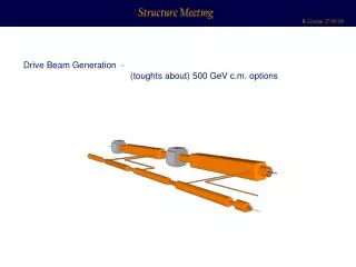
Drive beam generation
Drive beam generation. B. Jeanneret CLIC-ACE , may 2009 W ith material and advice from E. Adli , C.Biscari , R. Corsini , D.Schulte , F. Stulle. 326 klystrons 33 MW, 139 m s. combiner rings Circumferences delay loop 72.4 m CR1 144.8 m CR2 434.3 m.

Drive beam generation
E N D
Presentation Transcript
Drive beamgeneration B. Jeanneret CLIC-ACE , may 2009 Withmaterial and advicefrom E. Adli, C.Biscari, R. Corsini, D.Schulte, F. Stulle
326 klystrons 33 MW, 139 ms combiner rings Circumferences delay loop 72.4 m CR1 144.8 m CR2 434.3 m drive beam accelerator 2.38 GeV, 1.0 GHz CR1 CR1 1 km delay loop CR2 326 klystrons 33 MW, 139 ms drive beam accelerator 2.38 GeV, 1.0 GHz 1 km delay loop CR2 decelerator, 24 sectors of 868 m BDS 2.75 km BDS 2.75 km BC2 BC2 245m 245m IP1 e- main linac , 12 GHz, 100 MV/m, 20.85 km e+ main linac TA R=120m TA R=120m 47.9 km CLIC 3 TeV booster linac, 9 GeV, 2 GHz or 4 GHz ? BC1 e- injector 2.4 GeV e+ injector, 2.4 GeV e+ DR 365m e- DR 365m
Drive beamparameters 3 TeV 500 GeV R. Corsini, ACE sep08 106 A 2.54 GeV
Frequency multiplication,transfer, compression • OPTICS : DL, CR1, CR2, DBTL, TAs • BEAM DYNAMICS • GRADIENT AND BUNCH POPULATION • PHASE ERROR, PHASE CONTROL
CR1 arc cell C. Biscari, BJ PAC09 Quad-triplet : Sextupoles : All thiswouldideallyrequires 3 families of sextupolesatwell Defined phase advances (x and y) In practice : • - Not enough ∆µ/per cell , ratio D/ßinadequate ,… • dp = 0.02 large higher-ordereffectswithmanysextupoles • presently, explore with 1 familyonly
CR1 optics and 6D-tracking Withonly one family of sextupoles Spaced by ∆µx=3π/2 δp OK up to Jx,y= 3 • Furtherwork : • Workoff-energy to avoid large ∂p <0 • Full 6D trackingwitherrors, etc
PresentTurn-Around • 80m-long vs. 146m/CR1 • Twice more dipoles (accept. CSR) • Larger D/r • stronger quads • More aberrations, … • Correcting longitudinal and transverse phase space simultaneously not possible COST : Presently DBTL + 48 TA : 3% of total LTA 2LTA : 3.7% of total • Need new TA optics • similar to CR1 with LTA ≈ 150m
Delay Line • Presently : Layoutis a ring • Constraint : LDL = 73 m (beam train length) • As with TA : transverse chromaticeffects • SAME CURE : longer length • Go to a ‘Ω’ – shape Lloop = 135m Lstraight = 62 m Total extra-length : Lloop+Lstraight-∆L = 123 m (smallextra-cost ) Straight segment : Veryuseful for beam diagnostics AfterLinac FromLinac To CR1
CR2 / Down to tunnel /DBLongTLOptics • CR2 • LCR2 = 438 m • Not studiedat 2ndorder • But lengthcomfortable a priori not problematic • Down to tunnel • No studied • Common tunnel with Main Beam • Main beam more critical (vertical bends vs. Smallεy, mayrequireεy⇔εx) • A priori, not critical for Drive Beam • Long Transfer line • L= 20 km, simple FODO • Long cellsavoids large chromaticdetuning and filamentation • Needslimitedbeambasedalignment • No critical issues, see CLIC Note 760
Beamdynamicsfrom DL DECEL • Presented by R. Corsiniat ACE-sep08, seealso CLIC Note 761 • N-bunchresistivewallinstabilities • Largeeffect (3000 bunches, 5 1010e-(8 nC), spaced by 2.5 cm • W⊥ ~ a-3 CURE : use vac. Chamberwith large radius (copper) • Long transfer line (L= 20 km, large β’s) : a = 100 mm • Otherlines : : a = 25 mm • Vacuum • e- ionise and confine +ions • ∆µ betweenhead and tail of trains correctability, filamentation • Beam/ion instabilities • CURE : p < 10-10 Torr . Reachablewith getter + bake-out • ISSUE : “not more than“ COST (budgetedalready) • Emmitancegrowthsmall
RF deflectors in DL,CR1,CR2 • OK in CTF3 • But largercurrent in CLIC 100 A vs. 12A, whilehigherenergyhelps • Need more work in order to fix a ‘level of criticality’ vs. Collective effects • optimize ring tune for min. transverse excitation by deflector(R.Corsini, D. Schulte) Transverse position errorat the entrance of the Decelerator • ∆x/σβ =0.3 for <5% increase of amplitude at the DECEL exit (E. Adli) • Atdeflectors ( β=15m, ε=2⋅10-8 m) , σ’= 4⋅10-5 rad • Deflector kick Kd = 5⋅10-3 rad • Beamwillpassthroughndefl = 9 deflectors (DL 2, CR1 3, CR2 4) Remains to translate this Intodetailedspecification Similarly, withnkickkickers (CR1,CR2,in-TA) :
Incoherent synchrotron radiation • X-ray @ 6 keV : L_absorption = 50 µm (Aluminium) • Impact angle : ~ 0.2 rad • ∆T = 80 oK @ 50 Hz • Risk of rapidageing ∆x = 10 µm TIME STRUCTURE • OveralldE/E of ISR varies between • Trains travelling : • MIN : No DL, 1×CR1, 1×CR2 • MAX : 1×DL, 3×CR1, 4×CR2 • MaxdE/E = 2 o/oo • Converts to dz after last chicane before DECEL • 1% longitudinal z-pitch modulation R56 = -0.33 m • Cure : • make the DL, CR1,CR2 longer accordingly • complicates the feed-forwardφ–correction • (seeslide 20) 24 bunches x 121
Tolerance on Phase and Gradient • Luminosity and understanding/adjustment of the BeamDelivery and of the Final Focus D.Schulte & R.Tomas, PAC09 Not muchmargin on these
Gradient error for MB A bunch of the main beamseealways the gradient as built-up by the same nb = 0.5f0⋅τfill-MBAS≅ 400 DB bunches ahead of it MB DB With N the bunch population , And ‘inc’ as for ‘per sector’ At the entrance of the DECEL Stability of the DB in the DECEL : An overcurrent of 1% over τfill-PETS≡ 10 b. makesthe last bunch of theseunstable Before the end of the DECEL Stability over a whole cycle :
Tolerance on DB bunch population • Losses : constant part isharmless (adjustNsource ) • Erratic part : • transverse n-poles in RF structures, RF deflectors, magnets • Badlyunderstoodoptics (chromaticerrors) • Time dependenterror in kickers • Not explored as yet. • Untilwe know more about loss control : Maybestilloptimistic Need a more elaborate Statistical model Togetherwith :
Timing and feed-back strategy in the tunnel • To relax on δφ : feed-forward& back beforeentering the DECEL Notional, as for now 9 GeV MB as a fastclock Timing line A B DB ∆t to: injectors DB & MB Damp. Rings MB TA DB TAs @50 Hz TA C E D MB to IP Phase from B, EnergyjitterδE from A&B, Phase correction for δE C&D, Phase error MB/DB , to synchronize theinjectorlinacs Open issue: frequency band of δE correction
326 klystrons 33 MW, 139 ms combiner rings Circumferences delay loop 72.4 m CR1 144.8 m CR2 434.3 m drive beam accelerator 2.38 GeV, 1.0 GHz CR1 CR1 1 km delay loop CR2 326 klystrons 33 MW, 139 ms drive beam accelerator 2.38 GeV, 1.0 GHz 1 km delay loop CR2 decelerator, 24 sectors of 868 m BDS 2.75 km BDS 2.75 km BC2 BC2 245m 245m IP1 e- main linac , 12 GHz, 100 MV/m, 20.85 km e+ main linac TA R=120m TA R=120m 47.9 km CLIC 3 TeV booster linac, 9 GeV, 2 GHz or 4 GHz ? BC1 e- injector 2.4 GeV e+ injector, 2.4 GeV e+ DR 365m e- DR 365m
Phase control - I At 12 GHz • measurement of the 9 GeV MB ( keep in memory for T = [0..23] × 6 μs] ) • error in the 9 GeV MB fromInjector and in the MB-TA • DB TA length must bevery stable ⇔ magnetstability to bespecified • measurement of the DB • error of the feed-forwardadjustement of the chicane • transmission error in the timing system • bandwidthlimit for correction • periodicdE/E structure complicating the measurement (slide 13) • Path-lengths variations to beworked-outeverywhere Scheme : correct the phase withfastfeed-forward in the final chicane and slow feed-back to the injectors. Ingredients : J.Sladenproposed a Solution,down to 20 fs cost
Phase control – II : data L0 Chicane after TA α • Tolerance on α : • 1/10 δztol • 4 magnets L0 = 8mα= 0.1 rad Use staticmagnets + variable deflectors for range δφr=10o Erk willsay ‘red’ or ‘black’ Range insidewhich correction applies Withfeed-forward : relax for linac (Need room for feed-forwardoverallerrorkeep 0.2o for coh & inc in DB Linac)
Decelerator : conclusions (from E. Adli, last ACE) • Simulations gives reasonable confidence for minimum-loss transport of the decelerator beam • Beam-Based Alignment is needed, and Dispersion-Free Steering seems to be an excellent alternative • Dispersion-Free Steering comes almost "for free" with the use of delayed switching • Tune-up procedures must be applied • Simulations need to be benchmarked and technology needs to be proven: TBTS and TBL PETS Internaltolerances, perf,… : not discussedhere r0 = 3.5 mm : nominal max beam enveloppe Riris = 11.5 mm Dynamic tolerances Static tolerances
Summary and close future (CDR) • Most critical issues • Phase control dφ = 0.2o ↔ chicane / feed-forward / timing strategy • Bunchcurrent↔ source and loss control • RF deflectors ↔ design, tolerance,beaminstabilities • ISR absorption ↔ thermal stress, materials • For CDR (proposal) • Full opticsstudy of CR1 ↔ 6D chrom, Lengthadjustment (If OK : DL, CR2 , TA granted) • Coordinated effort for dφ by RF/CO/BI/ABP • Betterstatistical model for Ibunch, sources, losses
Chicanes and compression at the end of the Turn-around δE δE F. Stulle σδE=3e-3 z z σuδE= 2.5e-4 σ1,z=2mm σ2,z=1mm Presently : R56 = (σ2,z-σ1,z)/σδE = - 0.33 m • This value is large and convertsenergyjittersinto large phase errors • Make use of the larger possible momentumwindow of ∆E = ±2% • σδE=3e-3σδE=6e-3 ⇒ R56 = -0.16 m More comfortable, but a new studyisneeded (both chicane and chirp in DB Linac)