LEARNING OBJECTIVES
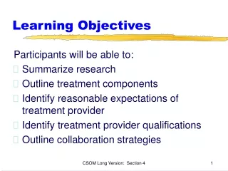
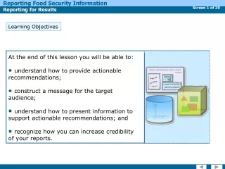
LEARNING OBJECTIVES. 1. Define the term modem. 2. Define the term baud. 3. Describe the three types of modulation commonly used in data communications. 4. Explain how baud and bit rate can differ. 5. Compare hardware- and software-oriented (code control) protocols.

LEARNING OBJECTIVES
E N D
Presentation Transcript
LEARNING OBJECTIVES 1. Define the term modem. 2. Define the term baud. 3. Describe the three types of modulation commonly used in data communications. 4. Explain how baud and bit rate can differ. 5. Compare hardware- and software-oriented (code control) protocols. 6. Describe steps to troubleshoot modem problems. 7. Differentiate among typical LAN topologies. 8. Describe the operation and hardware of an Ethernet LAN system. 9. Differentiate among different types of network media (10base2, 10base5, and so on). 10. Describe the operation and hardware of an Arcnet LAN system. 11. Describe steps to troubleshoot LAN networking problems. 12. Define the term wide area network (WAN). 13. Discuss basic concepts relating to Internet access (such as dial-up ISP connections). 14. Describe the function of routers, hubs, and bridges in network systems. 15. Discuss ISDN connections.
16. Describe FTP operations. 17. Discuss common Internet concepts and terminology (such as email). 18. Identify the purpose of the World Wide Web. 19. Discuss the purpose and use of on Internet browser. 20. Describe steps to troubleshoot WAN networking problems.
Generally, the most difficult aspect of connecting peripheral equipment to a computer is obtaining the proper interfacing and cabling.
In its simplest form, a modem consists of two major blocks: a modulator and a demodulator. The modulator is a transmitter that converts the parallel computer data into a serial format for transmission. The demodulator is the receiver that accepts the serial transmission format and converts it into a parallel format usable by the computer or peripheral.
The standard telephone system accommodates a range of frequencies between 300Hz and 3300Hz, or a bandwidth of 3000Hz. This is quite adequate for transmitting voice, but it severely distorts digital data. To use the audio characteristics of the phone lines to their best advantage, the modem encodes the digital 1s and 0s into analog signals within this bandwidth.
In addition to modulation techniques, advanced modems use data compression techniques to reduce the volume of data that must be transmitted. These data compression schemes are similar in operation to the techniques used with hard-disk drive recordings, tape back-up systems, and the audio/video digitizers described earlier in this text.
Two techniques exist for synchronizing the timing of data transmission between devices. The first method, known as synchronous transmission, places timing synchronization signals at the beginning of each data block to synchronize the transmitter and the receiver.
The other technique, called asynchronous transmission, places a synchronizing bit at the beginning and end of each eight-bit character.
To maintain an orderly flow of information between the computer and the modem (and between the modem and another modem) a protocol, or set of rules governing the transfer of information, must be in place.
The RS-232C standard identifies communication equipment using two categories: Data terminal equipment (DTE), usually a computer Data communication equipment (DCE), usually a modem
These five types of protocols can be broken down into two distinct classes: Hardware-oriented protocols Control code-oriented protocols
Of the control code class of protocols, three types are in widespread use: X-OFF/X-ON ACK/NAK ETX/ACK
Some of the more common protocols include the following: Xmodem Ymodem Zmodem Kermit
There are three basic conditions during the operation of the modem: Dialing Data exchange (the call) Answering
During the data transfer, both modems monitor the signal level of the carrier to prevent the transfer of false data due to signal deterioration. If the carrier signal strength drops below some predetermined threshold level or is lost for a given length of time, one or both modems will initiate automatic disconnect procedures.
Notable advanced UART versions include the 16450 and 16550. The 16450 was the 16-bit improvement of the 8250, and the 16550 was a high-performance UART with an onboard 16-byte buffer.
Two serial ports are normally provided in a PC-compatible system: RS-232-1 RS-232-2
TX-RD buffer (3F8/2F8h): This address selects the received data register, which holds the received character if the UART is in read configuration. Conversely, the transmitter holding register is accessed by the same address when the UART is in write configuration and bit-7 is low. If bit-7 is high, this address accesses the least significant byte (LSB) of the programmable baud-rate generator for initialization. (CONTINUED)
Interrupt enable register (3F9/2F9h): The bits of this register enable four different UART interrupts, which, in turn, activate the chip’s INTRPT output. This address also depends on bit 7 of the line-control register. The interrupt enable register is selected by bit 7 being low. If bit 7 is high, this address selects the most significant byte (MSB) of the programmable baud-rate generator for initialization. (CONTINUED)
Interrupt identification register (3FA/2FAh): The contents of this register are used to prioritize four interrupt levels in the UART. The bits of the register are used by software to identify the highest priority interrupt that may be pending and lock out all other interrupts until that particular interrupt has been serviced. (CONTINUED)
Line-control register (3FB/2FBh): The contents of this register are used to define the format of the port’s data exchange. The logic level of the various bits of this register define parameters such as word length, number of stop bits, and the type of parity used. Modem-control register (3FC/2FCh): The bits of this register control the DTE/DCE interface (in particular, the DTR and RTS lines). One bit of this register is used by software to provide loopback diagnostic testing. (CONTINUED)
Line status register (3FD/2FDh): This register provides the system unit with status information concerning data transfers. This information includes data ready in the receiver register, receiver register overrun errors, parity errors, framing errors, transmitter holding register empty, and transmitter shift register empty. Modem status register (3FE/2FEh): The contents of this register indicate the status of the DTE/DCE control lines. These lines include the CTS, DSR, RI, and RLSD lines.
All modems require software to control the communication session. This software is typically included with the purchase of the modem. At the fundamental instruction level, most modems use a set of commands known as the Hayes-compatible command set.
Table 11-4: The AT Command Set Summary * Default
Table 11-4: The AT Command Set Summary (CONTINUED) * Default
You should mentally divide the Troubleshooting Modems section into two segments: External modems Internal modems
Typical symptoms associated with modem failures include the following: No response occurs from the modem. The modem does not dial out. The modem does not connect after the number has been dialed. The modem does not transmit after making connection with remote unit. The modem cannot be installed properly for operation. Garbled messages are transmitted. A communication session cannot be terminated. Files cannot be transferred.
As stated earlier, every COM port on a PC requires an IRQ line to signal the processor for attention. In most PC systems, two COM ports share the same IRQ line. The IRQ4 line works for COM1 and COM3, and the IRQ3 line works for COM2 and COM4. This is common in PC-compatibles. The technician must make sure that two devices are not set up to use the same IRQ channel.