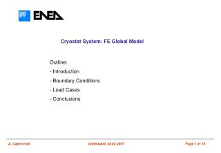
JWST Multi-Mega FE Model Studies
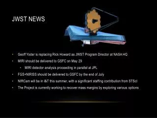
FINITE ELEMENT MODELING CONTINUOUS IMPROVEMENT FEMCI.GSFC.NASA.GOV NASA Goddard Space Flight Center Greenbelt, Maryland, USA Mechanical Systems Analysis and Simulation Branch, Code 542. JWST Multi-Mega FE Model Studies.

JWST Multi-Mega FE Model Studies
E N D
Presentation Transcript
FINITE ELEMENT MODELING CONTINUOUS IMPROVEMENT FEMCI.GSFC.NASA.GOV NASA Goddard Space Flight Center Greenbelt, Maryland, USA Mechanical Systems Analysis and Simulation Branch, Code 542 JWST Multi-Mega FE Model Studies Terry Fan/Swales AerospaceMark McGinnis/Swales AerospaceGlenn Grassi/MSC.SoftwareJohn Johnston, PH. D./GSFC May 4 & May 5, 2005
Objective & Summary • The objective of this study is to find an optimized computing solution • Enable Multi-mega model runs and, • Shorten the iteration times to a reasonable time frame • Summary • Benchmarking runs performed on several computer systems indicates that daily iteration is feasible • Super-element can be used to alleviate the hardware demanding, however it might prolong the iteration time. • Post processing of Mega-models may pose challenges. Well equipped computer will dramatically improve speed • RAM • CPU Speeds
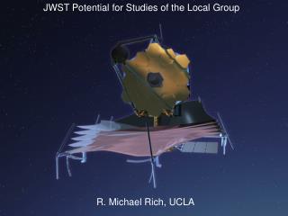
Introduction • The James Webb Space Telescope (JWST) structure system is operated at 30 Kelvin with nanometer-level performance requirements. • The main structure of the JWST is made of composite tubular components with a near-zero axial CTE and significant transverse CTE. • The traditional so-called stick model composed of beam elements cannot capture the transverse CTE, adhesive, clips, gussets, and other effects, which preliminary analyses indicate will have an first-order impact on the prediction distortions. • 8-noded brick elements were chosen to model the composite structures of JWST • To capture, transverse, through-the-thickness, and adhesive CTE effects • 30 millions degrees of freedom FEM is expected
Challenges & Issues • These are the largest structural models run at GSFC to date and are pushing/exceeding the limits of our computational resources • Pre/post-processing cumbersome • e.g. 30 min. to load model & generate pictures (2) of 4 MDOF model in FEMAP w/ a 1.6 GHz, 1 G RAM, Dell M60 precision workstation • Model loading time was reduced to 2 min. from 6 min. when RAM was increased to 2 GB compared • Integrations of Subsystem FEMs • I/F definitions among subsystems • Element types • Coordinates • Subsystems are modeled using MSC.Nastran and IDEAS • Incompatibility issues caused by IDEAS converted Nastran model
Challenges & Issues • MSC/Nastran and Pre- & Post-processors • How to run the Multi-mega model efficiently in MSC/Nastran • Super-element Analysis • Modeling guidelines • How to improve the pre- & post-processing time • What pre- & post-processors to use (FEMAP & Patran) • FEM mesh quality • Hardwires Specifications • CPU architecture, i.e. parallel processing • CPU speed • RAM • Disk Space & I/O configuration
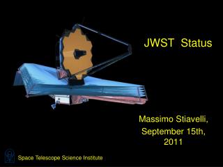
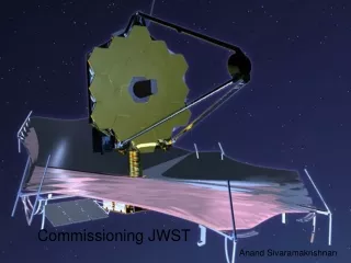
Primary Mirror (PM) • 18 (1.315 m) hex segments Optical Telescope Element (OTE) • ISIM • NIRCam, NIRSpec, MIRI & FGS Secondary Mirror (SM) • Sunshield • Passive cooling of ISIM/OTE to <40K Tower JWST Observatory Architecture
JWST Telescope Architecture Aft Optics Subsystem (A0S) Secondary Mirror Support Structure (SMSS) • Fixed tertiary mirror • Fine steering mirror • PM baffle/radiator ISIM Enclosure (IEA) Secondary Mirror Assembly (SMA) Primary Mirror Segment Assemblies (PMSA) • Light-weighted, semi-rigid segments • 18 modular units make up PM • Hexapod rigid body actuation, one RoC actuator PM BackPlane Assy (PMBA) • Supports 18 PMSAs, ISIM, IEC, Radiators, IOS, SMSS • Torque Box BSF Deployment Tower Subsystem (DTS)
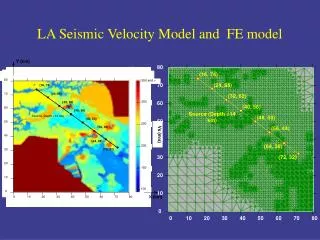
A PRELIMINARY 4 MDOF JWST FEM PMBA JWST system model Brick elements are used to model the tubular structure. Example shown is 4+ M DOFs model. ISIM
MSC.Software Mega Models Benchmarking (1/2) • Performed by MSC.Software • Three computing systems • Machine: Vesuvius • speed: 900 MHzop sys: HP-UX B.11.22ram: 8 Gbcpus: 4 Mckinley cpus • Machine: Sumatra - 4CPU - RAM=8Ggb • Hewlett Packard 9000 MODEL 9000/800/N4000-55 HP-UX (64-bit) B.11.00 • Machine: IA647 • Intel Itanium 2 /149 Linux 2.4.18-e.31smp • Nastran Version 2005.0.3 BETA • Residual Only - No Superelements • TEMPD • CPU=1 • SCR=YES • Buffsize=65537