Understanding HDLC and Data Link Protocols in OSI Model Communication
This chapter delves into data link protocols, particularly the High-level Data Link Control (HDLC) protocol, which is crucial for establishing data link layer specifications in the OSI model. It highlights the operational modes, station types (primary, secondary, combined), and configuration settings (unbalanced, symmetrical, balanced) of HDLC systems. The text also explains the importance of various HDLC frame types (I-Frames, S-Frames, U-Frames) and the bit stuffing technique essential for data integrity. Additionally, it discusses related link access procedures like LAPB, LAPD, and LAPM, showcasing their applications and functionalities in network communication.

Understanding HDLC and Data Link Protocols in OSI Model Communication
E N D
Presentation Transcript
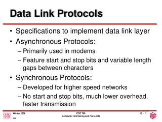
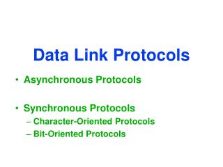
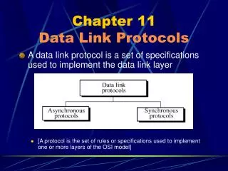
Chapter 11Data Link Protocols • A protocol in data communications is the set of rules of specifications used to implement one or more layers of the OSI model. • A data link protocol is a set of specifications used to implement the data link layer.
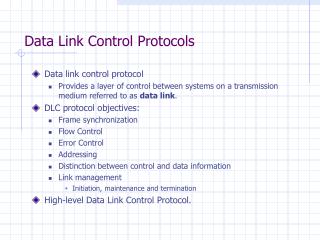
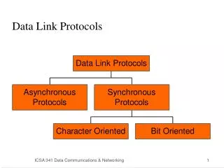
All bit-oriented protocols are related to high-level data link control (HDLC), a bit-oriented protocol published by ISO. HDLC supports both half-duplex and full-duplex modes in point to point and multipoint configurations. • System using HDLC can be characterized by their station types, their configurations, and their response modes.
Station in HDLC are of three types: Primary, secondary, and combined. A primary station send commands. A secondary station send responses. A combined station send commands and responses. • Configuration refer to the relationship of hardware devices on a link. Primary, secondary, and combined station can be configured in three ways: Unbalanced, symmetrical, and balanced.
Figure 11-14 HDLC Configuration
Figure 11-14-continued HDLC Configuration
Figure 11-14-continued HDLC Configuration
Figure 11-15 HDLC Modes NRM: A secondary device must have permission from the primary device before transmitting. ARM: A secondary may initiate a transmission without permission from the primary. ABM: All station arer equal and therefore only combined station connected in point to point are used.
Figure 11-16 HDLC Frame Types I-Frames are used only to transport control information, relating to user data.
Figure 11-16-continued HDLC Frame Types S-Frames are used only to transport control information, primarily data link layer flow and error controls.
Figure 11-16-continued HDLC Frame Types U-Frames are reserved for system management.
Figure 11-17 HDLC Flag Field
Bit Stuffing • Bit stuffing is the process of adding one extra 0 whenever there there are five consecutive 1s in the data so that the reciver does not mistake the data for a flag. Data sent 000111111001111101000 Frame sent Flag Address Control 000111110110011111001000 FCS Flag Frame Received Flag Address Control 000111110110011111001000 FCS Flag 000111111001111101000 Data Revived
Figure 11-18 Bit Stuffing 011111111000 0111110111000
Figure 11-19 HDLC Address Field If a primary station creates frame,it contains a to address.If a secondary creates the frame, it contains a from address
Figure 11-20 HDLC Control Field
Figure 11-21 Poll/Final
Figure 11-22 HDLC Information Field
Figure 11-23 HDLC FCS Field
Figure 11-25 Use of P/F Field
Figure 11-25-continued Use of P/F Field
Figure 11-25-continued Use of P/F Field
Figure 11-25-continued Use of P/F Field
Use of P/F Field Figure 11-25-continued
Figure 11-26 U-Frame Control Field Unnumbered frames are used to exchange session management and control information b/w connected devices. U-frame contain an information field, but one used for system management information not user data.
Figure 11-26-continued U-Frame Control Field
Figure 11-27 Polling Example
Selecting Example Figure 11-28
Peer-to-Peer Example Figure 11-29
Peer-to-Peer Example Figure 11-29-continued
Link Access Procedures LAPB LAPD LAPM • LAPB is used only in balanced configurations of two devices, where both devices are of the combined type. (ISDN). • LAPD It is used for out of band (control) signaling. • LAPM It is design to do asynchronous-synchronous conversion, error detection and retransmission.