Ethernet
Explanation of the detector drawings, field layer. 1. 3. 3. Cable and/or Bus. Ethernet. This depicts a task on a PC, each box does not necessarily correspond to a single PC. E. CAN bus. C. Profibus. P. PVSS II. Serial (RS232).

Ethernet
E N D
Presentation Transcript
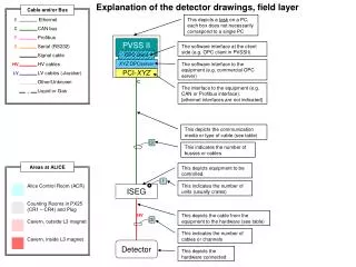
Explanation of the detector drawings, field layer 1 3 3 Cable and/or Bus Ethernet This depicts a task on a PC, each box does not necessarily correspond to a single PC E CAN bus C Profibus P PVSS II Serial (RS232) The software interface at the client side (e.g. OPC client in PVSSII) S Signal cable OPC client HV cables XYZ OPCserver The software interface to the equipment (e.g. commercial OPC server) HV LV cables (+busbar) PCI-XYZ LV Other/Unknown C The interface to the equipment (e.g. CAN or Profibus interface). [ethernet interfaces are not indicated] Liquid or Gas This depicts the communication media or type of cable (see table) This indicates the number of busses or cables Areas at ALICE This depicts equipment to be controlled. Alice Control Room (ACR) Counting Rooms in PX25 (CR1 – CR4) and Plug Cavern, outside L3 magnet Cavern, inside L3 magnet This indicates the number of units (usually crates) ISEG HV This depicts the cable from the equipment to the hardware (see table) This indicates the number of cables or channels Detector This depicts the hardware connected
“Generic” architecture for the DCS “back end” User interface; main console for detector operation This depicts a task on one or more PC’s, there is no one-to-one correspondence between boxes and PC’s Main PVSS tasks; interface to field layer, Finite State Machine, … Database tasks (reading and writing). [FSM?] Database(s) PVSS II PVSS II PVSS II OPCclient DIMclient User interface Ethernet PVSS II PVSS II OPC client OPC client CAEN OPCserver Wiener OPCserver DIMserver SchneiderOPCserver Field layer, with field layer processes
FMD 10 2 1 1 70 2 20 10 140 28/02/03 [FSM?] Database(s) PVSS II PVSS II PVSS II Control room (ACR) OPCclient DIMclient User interface Ethernet PVSS II PVSS II PVSS II OPS client OPC client OPC client CAEN OPCserver CAEN OPCserver DIMserver ? PCI-CAN? PCI-CAN? PCI-Profibus PCI-CAN? E E P C Ethernet is considered as alternative CAEN ? CAEN ? DDL TTC FMD-RCU (PCI? VME?) P? LVL0 trig HV LV LV 300? Detector Preamps FMD Digitizers High Voltage Preamps Digitizers Crate Control
FMD (no URD, information from pre-TDR and presentations) • High Voltage • 50 – 100V, 70 channels • What type of power supplies? • Can the power supplies be placed in the counting room? • What type of HV cable? Where do they enter the L3 magnet? • Low Voltage • ±2 V, 140 channels for preamps • ±5 V, 20 channels for digitizer boards • What type of power supplies? • What type of LV cable? What type of signal cable? Where do they enter the L3 magnet? • FEE • Digitizer boards: Monitor temperatures, download programs/parameters to FPGAs • Detector cooling • Forced air cooling: part of cooling of ITS-FMD-V0-T0 volume • Crate/Equipment Control • RCU board with DDL link: PCI / VME ? • Environment monitor • Temperature (other than Front-End), humidity etc: probably not • Other systems • Alignment? - possibly integrated with beam pipe alignment monitoring