Download
1 / 40
410 likes | 612 Vues
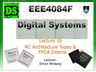
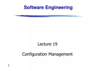
Lecture 19 Configuration architectures … & other FPGA-based RC Building Blocks. EEE4084F. Digital Systems. Lecturer: Simon Winberg. Configuration architectures Short video on NIOS II RC Building blocks Memories DMA Digital Signals Signal Latching. Lecture Overview.

E N D
Lecture 19 Configuration architectures … & other FPGA-based RC Building Blocks EEE4084F Digital Systems Lecturer: Simon Winberg
Configuration architectures • Short video on NIOS II • RC Building blocks • Memories • DMA • Digital Signals • Signal Latching Lecture Overview
Configuration Architectures RC Architecture
Configuration architecture = • Underlying circuitry that loads configuration data and keeps it at the correct locations Configuration Architectures Could store pre-configured bitmaps in memory on the platform without having to send it each time from the CPU. Include hardware for programming the hardware (instead of the slower process of e.g., programming devices via JTAG from the host) CPU Configuration requests Configuration controller FPGA Configuration data Finite State Machine ROM Configuration control Adapted from Hauck and Dehon Ch4 (2008)
Larger systems (e.g., the VCC) may have many FPGAs to be programmed) • Models: • Sequentially programming FPGAs by shifting in data • Multi-context – having a MUX choose which FPGA to program Configuration Architectures Configuration clock FPGA FPGA FPGA Configuration bit … IN IN IN OUT OUT OUT Configuration enable Adapted from Hauck and Dehon Ch4 (2008)
Partially reconfigurable systems • Not all configurations may need entire chip • Could leave parts of chips unallocated • Partial configuration decreases configuration time • Modifying part of a previously configured system • E.g., a placement and routing configuration based on a currently configured state Configuration Architectures Initial Configuration Updated Configuration
Block configurable architecture • Not the same as “logical blocks” in an FPGA • Relocating configurations to different blocks at run time also referred to as “swappable logic units” (SLUs) • Example: SCORE* relocatable architecture in which configurable blocks are handled in the same way as a virtual memory system Configuration Architectures * Capsi & DeHon and Wawrzynek. “A streaming multithreaded model” In Third workshop on media and stream processors. 2001
Reading • Hauck, Scott (1998). “The Roles of FPGAs in Reprogrammable Systems” In Proceedings of the IEEE. 86(4) pp. 615-639. Additional Reading
Short Video… Towards mobile augmented reality… Computer Vision Accelerator.wmv
Volatile Non-volatile Memory types
DRAM • Capacitor stores “memory” that leaks away and needs to be periodically refreshed • High memory capacity • SDRAM = Synchronous DRAM • Runs in synch with system* clock • DDR SDRAM = Double-data rate SDRAM, runs at 2x the system clock Volatile memory * Note the system clock in this case is closer to the “motherboard” clock. Usually considerably slower than the processor clock (standard DRAM may have its own even slower clock and synchronization hassles)
SRAM • Static RAM • Does not need refreshing • Uses “bistable latching circuitry”(i.e. a flip flop) to store each bit • Can be very fast compared to DRAM • A small amount of SRAM (~16 Kb) is typically used within a microcontroller / FPGA to hold things such as a boot loader and interrupt vectors, and as CACHE Volatile memory SR Latch to hold a bit of SRAM * SR Latch implemented using two NOR gates * * Images from http://en.wikipedia.org/wiki/Latch_(electronics)
BRAM or Block RAM • This refers to a small block of RAM (a few Kilobytes) integrated within the FPGA (connected some LBs) • Generally only found in higher-end FPGAs (e.g. 16Kb takes ~ 256K transistors if not more for connection and addressing logic) • Block SRAM is more common and easier to use; the FPGA may include Block DRAM • Generally can be set to RAM or ROM • As ROM it can be used as a (big) LUT • Usually not directly accessible form outside the FPGA (need to provide circuitry / softcore and comms protocol to access it from a PC) Volatile Memory
Under development • Z-RAM : Zero-capacitor RAM • Single transistor • Higher density than DRAM • Although it is called zero-capacitor, the capacitor is actually there in the form of a “floating body effect” caused by the transistor substrate • See: http://www.innovativesilicon.com/ Volatile memory
Trusty old ROM and EEPROM • Still widely used as it is highly robust • Current versions store large amounts of data • Fairly simple technology (i.e. fused connections) and (in EEPROM ability to fuse and then program/un-fuse connections) • Usually ROM is slower than RAM • Shadowing ROM (i.e. copy to RAM) to make it faster – especially for EEPROMs • EEPROM very slow write; faster read Non-Volatile memory
Flash memory • Can be electrically erased and programmed • High capacity (e.g., millions of bytes/chip) • Needs to be programmed one block at a time (~8Kb / block) • Erased (all bits in block set to 1) • Programmed one block at a time • Memory wear • Limited to about 100,000 erase – write cycles • Usually a file system (e.g. ext3) will keep track of bad sectors (i.e., mark deteriorated blocks). But this deterioration might happen a certain time after the erase and write is complete and verified. Non-Volatile Memory
NAND Flash memory model Image source: IEEE Electron Device Letters, Vol. 26, No. 8, AUGUST 2005, pg 564 Available at: http://koasas.kaist.ac.kr/bitstream/10203/1570/1/01468223.pdf * The above diagram provides a macro circuit model for a single flash memory cell, showing a Effective-Control-Gate (ECG) equivalent circuit and the Ideal-Current-Mirror (ICM) used to calculate the floating gate (FG*) voltage. MOSFET1 is the equivalent N-MOSFET model of a flash memory cell, and MOSFET2 is the model of a N-MOSFET test structure that is identical with the flash memory cell (excluding the short between FG and CG).
RC Building Blocks: Digital Signals and Data Transfers Reconfigurable Computing
Although our objective is towards parallel operations, there are still sequential issues involved, for example a device B waiting for a device A to provide input Furthermore the input to a device A might disappear (become invalid) before device A has completed its computations. Overview of digital signals Device A Device B In Out
There are other issues involved such as: • How does device A know when new data has arrived? • How does device B know when device A has completed? • What if both devices need to be clocked, but aren’t active all the time? • What if you want to share address and data lines? Overview of digital signals Device A Device B handshaking lines In Out
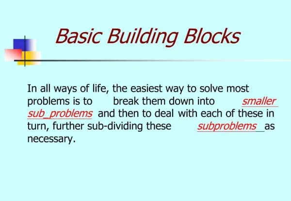
A sequential logic system typically involves two parts: • Storage (aka “bistable” device) • Combinational logic (OR, AND, etc gates) Digital logic modular design issues Combinational Logic Device INPUTS OUTPUTS Another combinational logic device(s) Another combinational logic device(s) Data Data potentially shared data busses, possibly 2 separate busses for full-duplex, one for read one for write control lines (e.g., do you want to read or write, are you done setting all the bits, etc.) Storage
Usually need the following • Address bus • Data bus • Control lines • Chip / Device select lines • Write enable lines • Read enable lines Digital Signals
RC Building Blocks: DMA – Efficient Data Transfer Reconfigurable Computing
Originally direct memory access (DMA) referred to a feature provided on a computer systems whereby peripherals within the computer can access the system memory for reading and/or writing independently of the central processing unit. This is still an appropriate definition; except rather consider DMA as a more general description, whereby separate hardware can both access memory directly (without the CPU doing any work), and can request the memory subsystem (really the DMAC) to perform memory copies or transfers. Direct Memory Access (DMA)
Typical computer design without DMA Memory (Device 0) In this approach, each peripheral signals the CPU and tells it to receive data and r/w memory address CS* CS0* address Address Decoder CPU CS1* IRQ data UART (Device 1) RD* CS2* CS* WR* IRQ … data RD* WR* Signals: Address : address line (e.g. 32 bits) Data : data line (e.g., 32 bits) IRQ : Interrupt ReQuest line CS* : Chip select (active low) RD* : Read enable (active low) WR*: Write enable (active low)
DMA : Direct Memory Access Memory address CPU Device (e.g., Graphics Card) IRQ DMA Controller IRQ data DMA Direct memory access is system in which memory is accessed without using the CPU. A certain stimulus (e.g. a device needing data sent/received) can have this data sent/received directly from/to a block of memory location via the DMA controller (DMAC). Peripherals such as ADCs, GPUs and Ethernet, which require frequent movements of memory, typically support DMA. DMA controllers can be configured to handle moving collected data from peripherals into specific memory locations (e.g., arrays directly accessible from a C program). Additional control logic is required to manage the sharing of the address and data bus. Further reading: http://www.freebsd.org/doc/en/books/developers-handbook/dma.html
Standard block transfer • DMAC does sequence of memory transfers • Load operation from source address, store operation to destination • Initiated under software control (e.g., copying data from one memory area to another) i.e., array X = array Y • Demand-mode transfer • Same as block transfer, but controlled by external device. I/O device requests and synchronizes the operation DMA configurations Ref: Catsoulis, J. (2003). Designing Embedded Hardware. O’Reilly.
Fly-by transfers • High speed operation • Memory and I/O on different bus • E.g., I/O given read request at same time that memory is given write request • Can simultaneously read/write I/O device and write/read memory • Data-chaining transfers • Linked list in memory • DMAC given pointer to descriptor • Descriptor indicates: size, src address, dest address, next descriptor DMA configurations
DMAC Modes of Operation 1 1 DMA Controller can support a range of modes. The three modes shown left are commonly supported. 1 2 2 2 3 w w w 3 Byte Mode Burst Mode Block Transfer Mode 123w123w123w… 12w2w2w3… 12w2w2www… Sequence of states CPU deactivates Adapted from source: http://calab.kaist.ac.kr
RC Building Blocks: Latching (capturing Signals) Reconfigurable Computing
In order to capture the signals, you need some storage Two basic types of storage: Digital Signal Capture and Storage Flip-flops Latches
Latches Q = D • Changes state when the input states change (referred to as “transparency”) • Can include an enable input bit – in which case the output (Q) is set to D only when the enable input is set. • Flip-flop Q = D (Q changes when clocked) • A flip-flop only change state whenthe clock is pulsed. Difference between latch and flip-flop
Latches are used more in asynchronous designs Flip-flips are used in synchronous designs A “synchronous design” is a system that contains a clock When to use a latch or a flip-flop You can of course mix synchronous and asynchronous, and this is particularly applicable to parallel systems in which different parts of the system may run at different speeds (e.g., the main processor working at 1GHz and specialized hardware possibly operating asynchronously as fast as their composite pipelined operations are able to complete)
SR Latch S-R Latch (set / reset latch) Symbol A basic latch has two stable states: State 1 Q = 1 not Q = 0 State 2 Q = 0 not Q = 1 And an unstable state in which both S and R are set (which can cause the Q and not Q lines to toggle)
Gated SR Latch: a latch with enable Combinational logic circuit with a clock (or enable) input connected Usually the type used in digital systems. It of course costs more in transistors!! or “gate” input Example signals Gated SR-Latch Symbol Only changed on clock pulse
Flip-flop The standard JK flip-flop is much the same as a gated SR latch, modified so that Q toggles when J = K = 1 JK flip-flop The D-type flip flop (which you may want to use in Prac3 to store data) is a JK flop flop modified (see left) to hold the state of input D at each clock pulse. D flip-flop
T-type Flip-flop The T-type flip-flops toggle the input. Q = not Q each time T is set to 1 when the clock pulses T flip-flop The D-type flip flop (which you may want to use in Prac3 to store data) is a JK flop flop modified (see left) to hold the state of input D at each clock pulse. D flip-flop
Preset and Clocking Preset line (PR) and clear line (CL) are asynchronous inputs used to set (to 1) or clear the value stored by the flip-flop.
Edge triggered devices A note on notation: Edge-triggered inputs are shown using a triangle. Negative edges triggered inputs are shown without a circle on the incoming line. in in Positive edge triggered Negative edge triggered
End of Lecture Any Question??