Chapter 2: Implementing VLANs in Campus Networks
780 likes | 1.04k Vues
Chapter 2: Implementing VLANs in Campus Networks. CCNP SWITCH: Implementing IP Switching. Chapter 2 Objectives. Design and plan VLANs, trunks, and addressing to meet business requirements, technical requirements, and constraints.

Chapter 2: Implementing VLANs in Campus Networks
E N D
Presentation Transcript
Chapter 2: Implementing VLANs in Campus Networks CCNP SWITCH: Implementing IP Switching
Chapter 2 Objectives • Design and plan VLANs, trunks, and addressing to meet business requirements, technical requirements, and constraints. • Configure VLANs and VLAN trunks in the campus network to support business and technical requirements. • Configure VTP in the campus network to support business and technical requirements. • Describe private VLANs and configure private VLANs in the campus network to support business and technical requirements. • Configure and verify an EtherChannel in a Layer 2 topology that contains bridging loops.
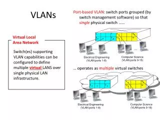
Virtual Local Area Network (VLAN) • A VLAN is a logical group of end devices. • Broadcasts are contained within VLANs. • Modern design has 1 VLAN = 1 IP subnet. • Trunks connect switches so as to transport multiple VLANs. • Layer 3 devices interconnect VLANs.
End-to-End VLANs • Each VLAN is distributed geographically throughout the network. • Users are grouped into each VLAN regardless of the physical location, theoretically easing network management. • As a user moves throughout a campus, the VLAN membership for that user remains the same. • Switches are configured for VTP server or client mode.
Local VLANs • Create local VLANs with physical boundaries in mind rather than job functions of the users. • Local VLANs exist between the access and distribution layers. • Traffic from a local VLAN is routed at the distribution and core levels. • Switches are configured in VTP transparent mode. • Spanning tree is used only to prevent inadvertent loops in the wiring closet. • One to three VLANs per access layer switch recommended.
VLANs in Enterprise Campus Design • VLANs used at the access layer should extend no further than their associated distribution switch. • Traffic is routed from the local VLAN as it is passed from the distribution layer into the core. • Blocks can contain one to three VLANs each. • STP is limited to access and distribution switches. • DHCP is used to assign IP addresses to users.
Best Practices for VLAN Design • One to three VLANs per access module and limit those VLANs to a couple of access switches and the distribution switches. • Avoid using VLAN 1 as the "blackhole" for all unused ports. Use a dedicated VLAN separate from VLAN 1 to assign all the unused ports. • Separate the voice VLANs, data VLANs, the management VLAN, the native VLAN, blackhole VLANs, and the default VLAN (VLAN 1). • Avoid VTP when using local VLANs; use manually allowed VLANs on trunks. • For trunk ports, turn off Dynamic Trunking Protocol (DTP) and configure trunking. Use IEEE 802.1Q rather than ISL because it has better support for QoS and is a standard protocol. • Manually configure access ports that are not specifically intended for a trunk link. • Prevent all data traffic from VLAN 1; only permit control protocols to run on VLAN 1 (DTP, VTP, STP BPDUs, PAgP, LACP, CDP, etc.). • Avoid using Telnet because of security risks; enable SSH support on management VLANs.
Configuration: Create a VLAN • To create a new VLAN in global configuration mode. Switch(config)# vlanvlan-id • vlan-id is 2-1001 or 1025-4094
Configuration: Name a VLAN • To name a VLAN in VLAN configuration mode. Switch(config-vlan)# namevlan-name • vlan-name is a descriptor for the VLAN. • Naming a VLAN is optional.
Example: Creating and Naming a VLAN • Enter global configuration mode: Switch# configure terminal • Create a new VLAN with a particular ID number: Switch(config)# vlan vlan-id • (Optional.) Name the VLAN: Switch(config-vlan)# name vlan-name Switch# configure terminal Switch(config)# vlan 5 Switch(config-vlan)# name Engineering Switch(config-vlan)# exit
Configuration: Disable Trunk Negotiation on a Port • To disable trunk negotiation on a switch port. Switch(config-if)# switchport mode access • This command is optional but is recommended for security purposes. An access port does not need to negotiate trunk formation.
Configuration: Macro for Access Port • To configure an optional macro for switch access ports. Switch(config-if)# switchport host • This command optimizes a Layer 2 port for a host connection. • This macro sets the port mode to access, enables spanning-tree portfast, and disables EtherChannel.
Configuration: Assign Port to VLAN • To assign a port to a VLAN in interface configuration mode. Switch(config-if)# switchport access vlan vlan-id • vlan-id is a previously created VLAN.
Example: Assigning a Port to a VLAN • Enter interface configuration mode: Switch(config)# interface interface-id • Configure a description for the device(s) connected to the port: Switch(config-if)# description string • Configure access port macro: Switch(config-if)# switchport host • Assign port to VLAN: Switch(config-if)# switchport access vlan vlan-id • Enable the interface: Switch(config-if)# no shutdown • Return to Privileged EXEC mode Switch(config-if)# end • Switch(config)# interface FastEthernet 5/6 • Switch(config-if)# description PC A • Switch(config-if)# switchport host • switchport mode will be set to access • spanning-tree portfast will be enabled • channel group will be disabled • Switch(config-if)# switchport access vlan 200 • Switch(config-if)# no shutdown • Switch(config-if)# end
Verification: VLAN Configuration • The show vlan command and its derivatives are the most useful commands for displaying information related to VLANs. The following two forms have the same output. Switch# show vlan id 3 VLAN Name Status Ports ---- -------------------------------- --------- ------------------------------- 3 VLAN0003 active Fa0/1 VLAN Type SAID MTU Parent RingNo BridgeNo Stp BrdgMode Trans1 Trans2 ---- ----- ---------- ----- ------ ------ -------- ---- -------- ------ ------ 3 enet 100003 1500 - - - - - 0 0 Switch# show vlan name VLAN0003 VLAN Name Status Ports ---- -------------------------------- --------- --------------------- 3 VLAN0003 active Fa0/1 VLAN Type SAID MTU Parent RingNo BridgeNo Stp BrdgMode Trans1 Trans2 ---- ----- ---------- ----- ------ ------ -------- ---- -------- ------ ------ 3 enet 100003 1500 - - - - - 0 0
Verification: Interface Configuration • The show running-config command has an interface keyword option to allow for interface-specific output. Switch# show running-config interface FastEthernet 5/6 Building configuration... ! Current configuration :33 bytes interface FastEthernet 5/6 switchport access vlan 200 switchport mode access switchport host end
Verification: Switch Port Configuration • One of the most useful commands for showing VLAN configuration information specific to a switch port is the show interfaces interface_id switchportcommand. Switch# show interfaces f0/18 switchport Name: Fa0/18 Switchport: Enabled Administrative Mode: static access Operational Mode: down Administrative Trunking Encapsulation: dot1q Negotiation of Trunking: Off Access Mode VLAN: 20 (VLAN0020) Trunking Native Mode VLAN: 1 (default) Administrative Native VLAN tagging: enabled Voice VLAN: 150 (VLAN0150) <output omitted> Operational private-vlan: none Trunking VLANs Enabled: ALL Pruning VLANs Enabled: 2-1001 Capture Mode Disabled Capture VLANs Allowed: ALL
Verification: MAC Address Information • You can view MAC address information specific to an interface and an associated VLAN. Switch# show mac-address-table interface GigabitEthernet 0/1 vlan 1 Mac Address Table ------------------------------------------ Vlan Mac Address Type Ports ---- ----------- ---- ----- 1 0008.2199.2bc1 DYNAMIC Gi0/1 Total Mac Addresses for this criterion: 1
VLAN Trunking • Trunks carry the traffic for multiple VLANs across a single physical link (multiplexing). Trunking is used to extend Layer 2 operations across an entire network. • The host on the left in VLAN 2 can communicate with the host on the right in VLAN 2 via the trunk link; over the same trunk link, the hosts on VLAN 1 can communicate simultaneously.
VLAN Trunking with Inter-Switch Link (ISL) • ISL is Cisco-proprietary trunking protocol. • ISL is nearly obsolete. • ISL encapsulates Ethernet frames, adding 30 bytes of overhead. • ISL is supported on non-access-layer Cisco switches.
VLAN Trunking with IEEE 802.1Q • 802.1Q is a widely supported industry-standard protocol. • IEEE 802.1Q has smaller frame overhead than ISL. 802.1Q overhead is 4 bytes. • 802.1Q has the 802.1p field for QoS support.
Native VLAN with IEEE 802.1Q • The 802.1Q standard specifies how the switch should handle untagged frames sent or received on an 802.1Q trunk port. • An 802.1Q trunk port is assigned a default PVID, which is associated with all untagged traffic on the port. All traffic with a null VLAN ID is assumed to belong to the port default PVID. A packet with a VLAN ID equal to the outgoing port default PVID is sent untagged. All other traffic is sent with a VLAN tag. • Proactively configuring both ends of an 802.1Q trunk link with a native VLAN distinct from all other VLANs is recommended.
Dynamic Trunking Protocol (DTP) • Access - Puts the interface into permanent non-trunking mode and negotiates to convert the link into a non-trunk link. The interface becomes a non-trunk interface even if the neighboring interface does not agree to the change. • Trunk - Puts the interface into permanent trunking mode and negotiates to convert the link into a trunk link. The interface becomes a trunk interface even if the neighboring interface does not agree to the change. • Nonegotiate - Puts the interface into permanent trunking mode but prevents the interface from generating DTP frames. You must configure the neighboring interface manually as a trunk interface to establish a trunk link. Use this mode when connecting to a device that does not support DTP. • Dynamic desirable - Makes the interface actively attempt to convert the link to a trunk link. The interface becomes a trunk interface if the neighboring interface is set to trunk, desirable, or auto mode. • Dynamic auto - Makes the interface willing to convert the link to a trunk link. The interface becomes a trunk interface if the neighboring interface is set to trunk or desirable mode. This is the default mode for all Ethernet interfaces in Cisco IOS.
Design with VLAN Trunks Trunks interconnect access layer switches. Trunks connect access layer switches to distribution layer switches. Layer 3 links interconnect core and distribution layer switches. Access layer switches are configured in a spanning-tree, loop-free, V-shaped topology. If one distribution link fails, HSRP or VRRP provide an alternative default gateway. Recommended: turn off DTP and manually prune VLANs on trunks.
Configuring an Interface for Trunking • Select the encapsulation type: Switch(config-if)# switchport trunk encapsulation {isl | dot1q | negotiate} • Configure the interface as a Layer 2 trunk: Switch(config-if)# switchport mode {dynamic {auto | desirable} | trunk} • Specify the native VLAN: Switch(config-if)# switchport trunk native vlan vlan-id • Configure the allowable VLANs for this trunk: Switch(config-if)# switchport trunk allowed vlan {add | except | all | remove} vlan-id[,vlan-id[,vlan-id[,...]]] Switch(config)# interface FastEthernet 5/8 Switch(config-if)# switchport trunk encapsulation dot1q Switch(config-if)# switchport mode trunk Switch(config-if)# switchport nonegotiate optional Switch(config-if)# switchport trunk allowed vlan 1-100 Switch(config-if)# no shutdown Switch(config-if)# end
Verifying Trunk Configuration Switch# show running-config interface f5/8 Building configuration... Current configuration: ! interface FastEthernet5/8 switchport mode dynamic desirable switchport trunk encapsulation dot1q end Switch# show interfaces f5/8 switchport Name: Fa5/8 Switchport: Enabled Administrative Mode: dynamic desirable Operational Mode: trunk Administrative Trunking Encapsulation: negotiate Operational Trunking Encapsulation: dot1q Negotiation of Trunking: Enabled Access Mode VLAN: 1 (default) Trunking Native Mode VLAN: 1 (default) Trunking VLANs Enabled: ALL Pruning VLANs Enabled: 2-1001 Switch# show interfaces f5/8 trunk Port Mode Encapsulation Status Native vlan Fa5/8 desirable n-802.1q trunking 1 Port Vlans allowed on trunk Fa5/8 1-1005
Troubleshooting Trunk Links • Ensure that the Layer 2 interface mode configured on both ends of the link is valid. The trunk mode should be trunk or desirable for at least one side of the trunk. • Ensure that the trunk encapsulation type configured on both ends of the link is valid and compatible. • On IEEE 802.1Q trunks, make sure the native VLAN is the same on both ends of the trunk. • When using DTP, ensure that both ends of the link are in the same VTP domain.
VLAN Trunking Protocol (VTP) • VTP is a Cisco-proprietary protocol that automates the propagation of VLAN information between switches via trunk links. This minimizes misconfigurations and configuration inconsistencies. • VTP does not configure switch ports for VLAN membership. • Three types of VTP messages are sent via Layer 2 multicast on VLAN 1. • VTP domains define sets of interconnected switches sharing the same VTP configuration.
VTP Pruning VTP pruning prevents flooded traffic from propagating to switches that do not have members in specific VLANs. VTP pruning uses VLAN advertisements to determine when a trunk connection is flooding traffic needlessly. Switches 1 and 4 in the figure support ports statically configured in the Red VLAN. The broadcast traffic from Station A is not forwarded to Switches 3, 5, and 6 because traffic for the Red VLAN has been pruned on the links indicated on Switches 2 and 4.
VTP Versions • ThreeVTP versions: V1, V2, V3. • Versions are not interoperable (e.g., V2 supports token ring VLANs but V1 does not). • Unrecognized Type-Length-Value (TLV) configuration changes are propagated by V2 servers and clients and these unrecognized TLVs can be stored in NVRAM. • V1 transparent switches inspect VTP messages for the domain name and version and forward a message only if the version and domain name match. V2 transparent switches forward VTP messages in transparent mode without checking versions. • V2 performs VLAN consistency checks (VLAN names and values) only when you enter new information through the CLI or via SNMP. V2 does not perform checks when new information is obtained from a VTP message or when information is read from NVRAM. If the MD5 hash on a received VTP message is correct, V2 accepts the VTP message information.
VTP Message Types • Summary Advertisements • Subset Advertisements • Advertisement Requests
VTP Summary Advertisements • By default, Catalyst switches issue summary advertisements in 5-minute increments. Summary advertisements inform adjacent switches of the current VTP domain name and the configuration revision number. • When the switch receives a summary advertisement packet, the switch compares the VTP domain name to its own VTP domain name. If the name is different, the switch ignores the packet. If the name is the same, the switch then compares the configuration revision to its own revision. If its own configuration revision is higher or equal, the packet is ignored. If it is lower, an advertisement request is sent.
VTP Subset Advertisements • When you add, delete, or change a VLAN, the VTP server where the changes are made increments the configuration revision and issues a summary advertisement. One or several subset advertisements follow the summary advertisement. • A subset advertisement contains a list of VLAN information. If there are several VLANs, more than one subset advertisement can be required to advertise all the VLANs.
VTP Subset Advertisements • When you add, delete, or change a VLAN, the VTP server where the changes are made increments the configuration revision and issues a summary advertisement. One or several subset advertisements follow the summary advertisement. • A subset advertisement contains a list of VLAN information. If there are several VLANs, more than one subset advertisement can be required to advertise all the VLANs.
VTP Advertisement Requests • A switch issues a VTP advertisement request in these situations: • The switch has been reset. • The VTP domain name has been changed. • The switch has received a VTP summary advertisement with a higher configuration revision than its own. • Upon receipt of an advertisement request, a VTP device sends a summary advertisement. • One or more subset advertisements follow the summary advertisement.
VTP Authentication • VTP domains can be secured by using the VTP password feature. It is important to make sure that all the switches in the VTP domain have the same password and domain name; otherwise, a switch will not become a member of the VTP domain. Cisco switches use MD5 to encode passwords in 16-byte words. These passwords propagate inside VTP summary advertisements. In VTP, passwords are case-sensitive and can be 8 to 64 characters in length. The use of VTP authentication is a recommended practice. • By default, a Catalyst switch does not have a VTP password. The switch does not automatically set the password parameter, unlike other parameters that are set automatically when a VTP advertisement is received.
Configuring VTP • Step 1. Enter global configuration mode: Switch# configure terminal • Step 2. Configure the VTP mode as server: Switch(config)# vtp mode server • Step 3. Configure the domain name: Switch(config)# vtp domain domain_name • Step 4. (Optional.) Enable VTP version 2: Switch(config)# vtp version 2 • Step 5. (Optional.) Specify a VTP password: Switch(config)# vtp password password_string • Step 6. (Optional.) Enable VTP pruning in the management domain: Switch(config)# vtp pruning
VTP Configuration Example • This example creates a VTP server with domain name Modular_Form, password genus, and pruning enabled. Switch# configure terminal Switch(config)# vtp mode server Setting device to VTP SERVER mode. Switch(config)# vtp domain Modular_Form Switch(config)# vtp password genus Switch(config)# vtp pruning Switch(config)# end
Verifying VTP Configuration (1) • The most useful command for verifying VTP configuration is the show vtp status command. The output displayed includes the VTP version, the VTP configuration revision number, the number of VLANs supported locally, the VTP operating mode, the VTP domain name, and the VTP pruning mode. Switch# show vtp status VTP Version : 2 Configuration Revision : 247 Maximum VLANs supported locally : 1005 Number of existing VLANs : 33 VTP Operating Mode : Server VTP Domain Name : Modular_Form VTP Pruning Mode : Enabled VTP V2 Mode : Disabled VTP Traps Generation : Disabled MD5 digest : 0x45 0x52 0xB6 0xFD 0x63 0xC8 0x49 0x80 Configuration last modified by 0.0.0.0 at 8-12-99 15:04:4
Verifying VTP Configuration (2) • Use the show vtp counters command to display statistics about VTP operation. If there are any problems regarding the VTP operation, this command helps look for VTP message type updates. Switch# show vtp counters VTP statistics: Summary advertisements received : 7 Subset advertisements received : 5 Request advertisements received : 0 Summary advertisements transmitted : 997 Subset advertisements transmitted : 13 Request advertisements transmitted : 3 Number of config revision errors : 0 Number of config digest errors : 0 Number of V1 summary errors : 0 VTP pruning statistics: Trunk Join Transmitted Join Received Summary advts received from non-pruning-capable device ------ ---------------- ------------- ----------------- Fa5/8 43071 42766 5
VTP Troubleshooting • Check that switches are interconnected by active trunk links. • Check that the trunking protocol matches on opposite ends of a trunk link. • Check VTP domain name (case-sensitive) and password. • Check the VTP mode of the switches. • Check the VTP versions of the switches.
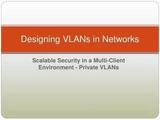
Motivation for Private VLANs • Service providers often have devices from multiple clients, in addition to their own servers, in a single Demilitarized Zone (DMZ) segment or VLAN. As security issues abound, it becomes more important to provide traffic isolation between devices, even though they might exist on the same Layer 3 segment and VLAN. • Most Cisco IOS-based switches implement private VLANs to keep some switch ports shared and some switch ports isolated, even though all ports remain in the same VLAN.