Download

1 / 17
190 likes | 399 Vues
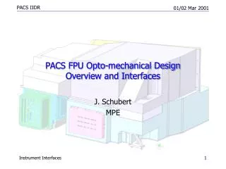
First-Order Opto-Mechanical Considerations in High Power Applications. Victor Villavicencio NGIT / Defense Group Technology Integration & Applications Operating Unit Science and Engineering Applications December 06. OUTLINE.

E N D
First-Order Opto-Mechanical Considerations in High Power Applications Victor Villavicencio NGIT / Defense Group Technology Integration & Applications Operating Unit Science and Engineering Applications December 06
OUTLINE • Geometric versus Diffraction Limited Spot Diameter Approximations • Optical Element Parameters • Materials Properties • Thermal Effects/ Athermalization Approximations • Scattering Approximations • Software Tools
For M2 > 6, use (Geometric) Spot Diameter Approximations RMS diameter = 0.7 Dz/Fn • For Diffraction Limited System, Spot Diameter is defined as 86% of encircled energy • For Geometric System, Spot Diameter is defined as • “greater than 50% of encircled energy is within 70% of the marginal ray diameter”
B’ B Thermal Effects on a Len Thickness and Radius of Curvature In isotropic materials, a temperature change makes inside Dimensions scale as outside Dimensions. A’ A A’ = DA + A B’ = DB + B DA = A aDT DB = B aDT Radius of Curvature, R, changes to R’, using the same thermal expansion equation.
Thermal Stress, s Use Superposition to Calculate stress due to temperature change For Glass, Do not exceed 1000 psi (7 MegaPascal) in tensile stress 50,000 psi (350 MPa) in compression stress
Thermo-Optic Coefficients, n, and CTE Values of Materials n ( x 10-6/ Celsius) Plastics - 20 thru –40 CTE of Common Materials , a (x 10-6 /Celsius) Aluminum 6061 / Brass 23.4 416 Stainless 9.9 Invar35 0.6 Titanium 8.7 Glass 3 to 7 Plastics 50 – 80 Adhesives 40 – 1000 Infrared Glasses 2 thru 20
Total Integrated Scatter Measurement TISb(s,l) = s / ( s + r) = 1 – e –(4 pcosi/l) Calculation for Straylight for 10W, 1.3 micron, 4% Fresnel Reflection: ( Powerreflected )* Eq. 1 = (10 * 0.04) * (4 Pi 0.08)^2 = 0.54 Watts backwards scattered.
Back Scatter Approximation The approximate backscatter TIS is shown below: TISb(s,l)= As shown above, the approximate TIS is good for σ < ~λ/25. That is, for s(l)/l > 0.04, the approximation underestimates the exact exponential form TIS.
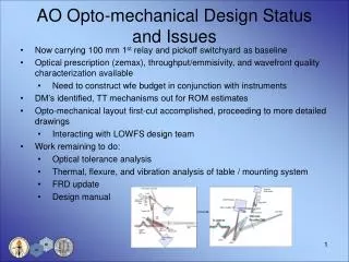
U.S. Opto-mechanical design between various disciplines Zernike Analysis Optics Zemax CodeV ASAP TracePro 4Sight Vision SigFit Structures NASTRAN ANSYS COSMOS Other Disciplines Databases and Translator Software Fluid Mechanics Acoustics 3D Graphics CAD/CAM AutoCAD SolidWorks ProEngineer Control Systems Heat Transfer Sinda TAP MITAS Matlab/Simulink LabView/LabWindows
Conclusion • Thermal effects and scattering first order calculations for high power applications. • In your experimental setup, use the incoherent rms spot size equation to determine spot size. This provides the largest (worst case) spot size. • TIS calculations are always conservative since it deals with surface roughness scatter. Internal straie /inclusions/stress will only slightly increase this TIS calculations. • To achieve geometrical approximations, thermal effects must be taken into account for plastics optics over DT = 20 C or more or glass optics needing to operate over DT= 40 C or more. References • OPTI521 Class Notes, Fall, 2006. • Michael G. Dittman, Frank Grochocki, Kathleen Youngworth, No such thing as σ – flowdown and measurement of surface roughness requirements, Optical Systems Degradation, Contamination, and Stray Light: Effects, Measurements, and Control II, edited by O. Manuel Uy, Sharon A. Straka, John C. Fleming, Michael G. Dittman, SPIE Vol. 6291. • Frank DeWitt IV, Georg Nadorff, Rigid Body Movements of Optical Elements due to Opto-Mechanical Factors Optical Modeling and Performance Predictions II, edited by Mark A. Kahan, SPIE Vol. 5867, (2005)
Diffraction Limited Approximations Applies to M^2 < 4 Laser Systems Minimum Spot Diameter = 2.44 l F/# Depth of Focus = +/- 2 l (F/#)2 F/# is the “F-number” Singlet
Various Mounting Techniques a) Edge-mounted b) Surface-centered c) Cell-mounted Sag R r Sag z R
Calculating Tilt Figure 7 Accounting for tilt of a edge mounted element [3] Using a semidiameter (SD) of 5 mm, R = 162 mm and a gap of 0.7 mm , a tilt of 2 degrees was calculated. This tilt value is used to determine effects on image quality using Zemax.
Calculating the Change in Focal Length for a Plastic Singlet, f = 25 mm, 10 mm diameter. The focal length expands, due to the Dt = 40 C temperature rise, by