NAST-I Development History
NAST-I Development History. Developed by MIT Lincoln Laboratory in 18 months for NPOESS using a COTS BOMEM (now ABB) interferometer, detectors, and optics Flown aboard NASA's high-altitude ER-2, Northrop Grumman Proteus aircraft, and NASA’s WB-57

NAST-I Development History
E N D
Presentation Transcript
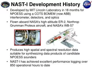
NAST-I Development History • Developed by MIT Lincoln Laboratory in 18 months for NPOESS using a COTS BOMEM (now ABB) interferometer, detectors, and optics • Flown aboard NASA's high-altitude ER-2, Northrop Grumman Proteus aircraft, and NASA’s WB-57 • Produces high spatial and spectral resolution data suitable for synthesizing data products of candidate NPOESS sounders • NAST-I has achieved excellent performance logging over 850 operational hours to date
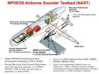
NAST-I Overview • Instrument Characteristics • infrared Michelson interferometer • (9000 spectral channels) • 3.5 – 16 microns @ 0.25 cm-1 • Aircraft Accommodation • ER-2 Super pod & Proteus Underbelly pod • Radiative Measurement Capability • calibrated radiances with • 0.5 K absolute accuracy, 0.1 K precision Spatial Resolution 130m/km flight alt. (2.6 km from 20km) Swath Width 2 km /km flight alt. (40 km from 20 km) Temperature (K) Water Vapor Mixing Ratio( Uncorrected) Relative humidity (%)
NAST Flight History ER-2 MAS • 1998-2004: 17 Missions • 152 Mission sorties • 850 Flight hours NAST-I S-HIS NAST-M Proteus S-HIS NAST-M NAST-I
NAST-I Major Characteristics Detector Characteristics LW band 7.8 – 16.1mm PC HgCdTe cooled to 77K MW band 4.8 – 7.8mm PC HgCdTe cooled to 77K SW band 3.7 – 4.8mm PV InSb cooled to 77K detector size 1 mm entrance pupil diameter 0.28in scan angle +/- 48.4maximum IFOV 7.45 collimated beam diam. in interferometer 1.5in beamsplitter/compensator 1.9in clear aperture KBr alignment technique dynamic based on HeNe laser OPD +/- 2.0cm (high resolution mode) OPD velocity 5.2cm/sec, RMS variation under 1% sweep time 0.77sec turnaround time 0.044sec Input Optics Micheleson Interferometer
Background Radiance in NAST-I • NAST-I operates at room temperature (ground and flight) • Cold field stop and baffles within detector package significantly reduce background radiation from surrounding structures • Some flux is modulated by the interferometer and detected NAST Detector Assembly Optical Bench
NAST-I System Diagram InputOptics AftOptics 1.2Gbyte disk cm sec temporal f (sec-1) spatial n (cm-1) IR Light Detectors and Preamplifiers Micheleson Interferometer optical signal (photons) flight computer electrical signal (V) Anti-aliasing filter A/D DSP Card PCI bus SCSI bus 133MHz Triton Pentium Single Board Computer
Scanning Interferometer Sounder 4 – 16 m NAST Layout In ER-2 SuperPod ER-2 at Patrick AFB MIT/RLE Microwave Sounder Electronics, Control & Navigation NASA ER-2 Processing & Recording NADIR 2.6km IFOV 20km Altitude +/- 23km Ground Swath
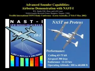
Proteus Configuration NAST-I 3.5 – 16micron @ 0.25 cm-1 • NAST-M • (54, 118 GHz)
WB-57 Pallet Configuration NAST-I Rack designed by SED/MSB and fabricated by SED fab WB-57 Pallet
Background Brightness Temperature Theoretical Hot, Amb cal target flux Hot, Amb cal target measurement Calibrated Responsivity Background Flux Brightness Temp • Background estimate is obtained from: • Background is 180o out-of-phase with scene radiation • Spectral signature indicates it is reflected off of Black Anodized Al • Mounts, and most structures on the bench are Black Anodized Al • Bkgd differs from ground to flight • Including background in alignment NEdN calculation is essential for obtaining accurate results Simulate Background using Black Anodize Reflectivity Tsimulated =>[Ranodize * BB(285 K)]+BB(240 K) Estimated Ranodize Measured Ranodize ** Ranodize measurements were performed on Black Anodize Al similar to that found on NAST-I
Modification History MW detector LW detector • Beamsplitter replacement • Improved shock mounts/isolation • PID thermal control of canister • Circuit added to DA servo control to insert static offset in both sweep directions (UW) • Gain tuning of DA servo gains • Component replacement in DA servo and metrology laser electronics • LW detector, cooler, and optics SW detector
NAST-I Lessons Learned • Worked well • Integrated Dewar Cooler Assembly (IDCA) • Stirling cycle cooler • Reflective optical design • Coregistration • Bomem interferometer • MIT LL Porch swing • Simple design: reliability • What could be better • LW detector performance • Data collection • Data quicklook analysis • Vibration isolation • BS/CS wedge • More metrology signals • Improved GPS