Memory Management
Memory Management. Memory management. We have seen how CPU can be shared by a set of processes Improve system performance Process management Need to keep several process in memory Share memory Learn various techniques to manage memory Hardware dependent . Memory management.

Memory Management
E N D
Presentation Transcript
Memory management • We have seen how CPU can be shared by a set of processes • Improve system performance • Process management • Need to keep several process in memory • Share memory • Learn various techniques to manage memory • Hardware dependent
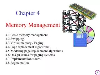
Memory management What are we going to learn? • Basic Memory Management: logical vs. physical address space, protection, contiguous memory allocation, paging, segmentation, segmentation with paging. • Virtual Memory:background, demand paging, performance, page replacement, page replacement algorithms (FCFS, LRU), allocation of frames, thrashing.
Background • Program must be brought (from disk) into memory • Fetch-decode-execute cycle • Memory unit only sees a stream of addresses + read requests, or address + data and write requests • Sequence of memory addresses generated by running program CPU
Background Multiple processes resides in memory • Protection of memory required to ensure correct operation 1. Protect OS 2. Protect user processes
Base and Limit Registers • A pair of baseandlimitregisters define the logical address space
Hardware Address Protection with Base and Limit Registers • OS loads the base & limit reg. • Privileged instruction
Address Binding • Process resides in main memory • Associate each data element with memory address • Further, addresses represented in different ways at different stages of a program’s life • Source code addresses usually symbolic • Compiled code addresses bind to relocatable addresses • i.e. “14 bytes from beginning of this module” • Linker or loader will bind relocatable addresses to absolute addresses • i.e. 74014
Binding of Instructions and Data to Memory • Address binding of instructions and data to memory addresses can happen at three different stages • Compile time: If memory location known a priori, absolute codecan be generated; must recompile code if starting location changes • Load time: Must generate relocatable code if memory location is not known at compile time • Execution time: If the process can be moved during its execution from one memory segment to another • Binding delayed until run time • Need hardware support for address maps (e.g., base and limitregisters)
Logical vs. Physical Address Space Logical address– generated by the CPU; also referred to as virtual address Physical address– address seen by the memory unit • Logical and physical addresses are the same in compile-time and load-time address-binding schemes; • logical (virtual) and physical addresses differ in execution-time address-binding scheme • Logical address space is the set of all logical addresses generated by a program • Physical address space is the set of all physical addresses generated by a program CPU
Memory-Management Unit (MMU) • Hardware device that at run time maps virtual to physical address • Many methods possible • To start, consider simple scheme where the value in the relocation register is added to every address generated by a user process at the time it is sent to memory • relocation register • MS-DOS on Intel 80x86 used 4 relocation registers • The user program deals with logical addresses (0 to max); it never sees the real physical addresses (R to R+max) • Say the logical address 25 • Execution-time binding occurs when reference is made to location in memory • Logical address bound to physical addresses
Contiguous Allocation Multiple processes resides in memory
Contiguous Allocation • Main memory usually divided into two partitions: • Resident operating system, usually held in low memory • User processes then held in high memory • Each process contained in single contiguous section of memory
Contiguous Allocation (Cont.) • Multiple-partition allocation • Divide memory into several Fixed size partition • Each partition stores one process • Degree of multiprogramming limited by number of partitions • If a partition is free, load process from job queue • MFT (IBM OS/360)
Contiguous Allocation (Cont.) • Multiple-partition allocation • Variable partition scheme • Hole – block of available memory; holes of various size are scattered throughout memory • Keeps a table of free memory • When a process arrives, it is allocated memory from a hole large enough to accommodate it • Process exiting frees its partition, adjacent free partitions combined • Operating system maintains information about:a) allocated partitions b) free partitions (hole) OS OS OS OS OS process 5 process 5 process 5 process 5 process 9 process 9 Hole process 8 process 10 process 2 process 2 process 2 process 2
Dynamic Storage-Allocation Problem How to satisfy a request of size n from a list of free holes? Dynamic storage allocation problem • First-fit: Allocate the first hole that is big enough • Best-fit: Allocate the smallest hole that is big enough; must search entire list, unless ordered by size • Produces the smallest leftover hole • Worst-fit: Allocate the largest hole; must also search entire list • Produces the largest leftover hole
Hardware Support for Relocation and Limit Registers • Relocation registers used to protect user processes from each other, and from changing operating-system code and data • Relocation register contains value of smallest physical address • Limit register contains range of logical addresses – each logical address must be less than the limit register • Context switch • MMU maps logical address dynamically
Fragmentation • Processes loaded and removed from memory • Memory is broken into little pieces • External Fragmentation– total memory space exists to satisfy a request, but it is not contiguous • First fit analysis reveals that given N blocks allocated, 0.5 N blocks lost to fragmentation • 1/3 may be unusable -> 50-percent rule
Fragmentation (Cont.) • Reduce external fragmentation by compaction • Shuffle memory contents to place all free memory together in one large block • Compaction is possible only if relocation is dynamic, and is done at execution time • Change relocation reg. • Cost • Internal Fragmentation– allocated memory may be slightly larger than requested memory; this size difference is memory internal to a partition, but not being used
Paging • Physical address space of a process can be noncontiguous; • process is allocated physical memory whenever the latter is available • Divide physical memory into fixed-sized blocks called frames • Size is power of 2, between 512 bytes and 16 Mbytes • Divide logical memory into blocks of same size called pages • To run a program of size N pages, need to find N free frames and load program • Backing store likewise split into pages • Set up a page table to translate logical to physical addresses • System keeps track of all free frames
Paging Model of Logical and Physical Memory page table to translate logical to physical addresses
Address Translation Scheme • Address generated by CPU is divided into: • Page number (p)– used as an index into a page table • which contains base address of each page in physical memory • Page offset (d)– offset within a page • combined with base address to define the physical memory address that is sent to the memory unit • For given logical address space 2m and page size2n offset page page offset page number p d m - n n
Paging Example Logical address 0 (0*4+0) Physical address: (5*4+0)=20 Logical address 3 (0*4+3) Physical address: (5*4+0)=23 Logical address 4 (1*4+0) Physical address: (6*4+0)=24 Logical address 13 (3*4+1) Physical address: (2*4+1) Logical address = 16 Page size=4 Physical memory=32 User’s view Run time address binding n=2 and m=4 32-byte memory and 4-byte pages
Paging • External fragmentation?? • Calculating internal fragmentation • Page size = 2,048 bytes • Process size = 72,766 bytes • 35 pages + 1,086 bytes • Internal fragmentation of 2,048 - 1,086 = 962 bytes • So small frame sizes desirable? • But each page table entry takes memory to track • Page sizes growing over time • Solaris supports two page sizes – 8 KB and 4 MB • User’s view and physical memory now very different • user view=> process contains in single contiguous memory space • By implementation process can only access its own memory • protection
Each page table entry 4 bytes (32 bits) long • Each entry can point to 232 page frames • If each frame is 4 KB • The system can address 244 bytes (16TB) of physical memory
Process P1 arrives • Requires n pages => n frames must be available • Allocate n frames to the process P1 • Create page table for P1
Free Frames Frame table RAM RAM After allocation Before allocation
Implementation of Page Table • For each process, Page table is kept in main memory • Page-table base register (PTBR)points to the page table • Page-table length register (PTLR)indicates size of the page table • In this scheme every data/instruction access requires two memory accesses • One for the page table and one for the data / instruction • The two memory access problem can be solved by the use of a special fast-lookup hardware cache called associative memory or translation look-aside buffers (TLBs)
Associative Memory • Associative memory – parallel search • Address translation (p, d) • If p is in associative register, get frame # out • Otherwise get frame # from page table in memory Page # Frame #
Implementation of Page Table • For each process, Page table is kept in main memory • Page-table base register (PTBR)points to the page table • Page-table length register (PTLR)indicates size of the page table • In this scheme every data/instruction access requires two memory accesses • One for the page table and one for the data / instruction • The two memory access problem can be solved by the use of a special fast-lookup hardware cache called associative memory or translation look-aside buffers (TLBs) • TLBs typically small (64 to 1,024 entries) • On a TLB miss, value is loaded into the TLB for faster access next time • Replacement policies must be considered (LRU) • Some entries can be wired down for permanent fast access • Some TLBs storeaddress-space identifiers (ASIDs) in each TLB entry – uniquely identifies each process (PID) to provide address-space protection for that process • Otherwise need to flush at every context switch
Effective Access Time • Associative Lookup = time unit • Can be < 10% of memory access time • Hit ratio = • Hit ratio – percentage of times that a page number is found in the associative registers; ratio related to size of TLB • Consider = 80%, = 20ns for TLB search, 100ns for memory access • Effective Access Time(EAT) EAT = (100 + ) + (200 + )(1 – ) • Consider = 80%, = 20ns for TLB search, 100ns for memory access • EAT = 0.80 x 120 + 0.20 x 220 = 140ns • Consider slower memory but better hit ratio -> = 98%, = 20ns for TLB search, 100ns for memory access • EAT = 0.98 x 120 + 0.02 x 220 = 122ns
Memory Protection • Memory protection implemented by associating protection bit with each frame to indicate if read-only or read-write access is allowed • Can also add more bits to indicate page execute-only, and so on • Valid-invalidbit attached to each entry in the page table: • “valid” indicates that the associated page is in the process’ logical address space, and is thus a legal page • “invalid” indicates that the page is not in the process’ logical address space • Or use PTLR • Any violations result in a trap to the kernel
Valid (v) or Invalid (i) Bit In A Page Table 14 bit address space (0 to 16383) Page size 2KB Process P1 uses only 0 to 10468 P2 P1 Internal fragmentation Use of PTLR (length)
Shared Pages Example • System with 40 users • Use common text editor • Text editor contains 150KB code 50KB data (page size 50KB) • 8000KB! • Shared code • One copy of read-only (reentrant) code shared among processes (i.e., text editors, compilers, window systems) • Code never changes during execution • Only one copy of the editor in the memory • Total memory consumption • 40*50+150=2150KB
Structure of the Page Table • Memory requirement for page table can get huge using straight-forward methods • Consider a 32-bit logical address space as on modern computers • Page size of 4 KB (212) • Page table would have 1 million entries 220 (232 / 212) • If each entry is 4 bytes -> 4 MB of physical address space / memory for page table alone • That amount of memory used to cost a lot • Don’t want to allocate that contiguously in main memory • Hierarchical Paging • Hashed Page Tables • Inverted Page Tables
Hierarchical Page Tables • Break up the page table into multiple pages • We then page the page table • A simple technique is a two-level page table
Two-Level Paging Example • A logical address (on 32-bit machine with 4KB page size) is divided into: • a page number consisting of 20 bits • a page offset consisting of 12 bits • Since the page table is paged, the page number is further divided into: • a 10-bit page number • a 10-bit page offset • Thus, a logical address is as follows: • where p1 is an index into the outer page table, and p2 is the displacement within the page of the inner page table page number page offset p2 p1 d 10 10 12
Two-Level Page-Table Scheme Each divided page table size=210 *4bytes=4KB =Page size d p1 p2
64-bit Logical Address Space • Even two-level paging scheme not sufficient • If page size is 4 KB (212) • Then page table has 252 entries • If two level scheme, inner page tables could be 210 4-byte entries • Address would look like • Outer page table has 242 entries or 244 bytes • One solution is to add a 2nd outer page table • But in the following example the 2nd outer page table is still 234 bytes in size • And possibly 4 memory access to get to one physical memory location inner page page offset outer page p2 p1 d 42 10 12
Hashed Page Tables • Common in virtual address spaces > 32 bits • The page number is hashed into a page table • This page table contains a chain of elements hashing to the same location • Each element contains (1) the page number (2) the value of the mapped page frame (3) a pointer to the next element • Virtual page numbers are compared in this chain searching for a match • If a match is found, the corresponding physical frame is extracted