Download
1 / 25
290 likes | 914 Vues
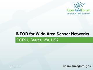
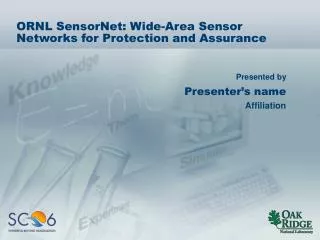
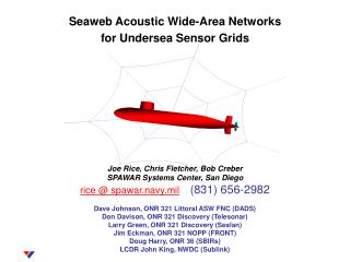
Seaweb Acoustic Wide-Area Networks for Undersea Sensor Grids. Joe Rice, Chris Fletcher, Bob Creber SPAWAR Systems Center, San Diego rice @ spawar.navy.mil (831) 656-2982 Dave Johnson, ONR 321 Littoral ASW FNC (DADS) Don Davison, ONR 321 Discovery (Telesonar)

E N D
Seaweb Acoustic Wide-Area Networks for Undersea Sensor Grids Joe Rice, Chris Fletcher, Bob Creber SPAWAR Systems Center, San Diego rice @ spawar.navy.mil(831) 656-2982 Dave Johnson, ONR 321 Littoral ASW FNC (DADS) Don Davison, ONR 321 Discovery (Telesonar) Larry Green, ONR 321 Discovery (Sealan) Jim Eckman, ONR 321 NOPP (FRONT) Doug Harry, ONR 36 (SBIRs) LCDR John King, NWDC (Sublink)
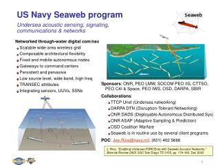
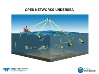
Seaweb Communication & NavigationCONCEPT OF OPERATIONS Use telesonar digital communications to form deployable autonomous distributed sensor networks with: • wide-area coverage • architectural flexibility • environmentally adaptive wireless links • self-configuring ad hoc topologies • fixed sensor nodes and repeater nodes • fixed and mobile peripheral nodes, e.g. bi-static projectors and UUVs • fixed and mobile gateway nodes linked to command centers submerged, afloat, aloft and ashore Extend network-centric C4ISR into the undersea battlespace Rice, “Telesonar signaling and seaweb underwater wireless networks,” Proc. NATO New Information Processing Techniques for Military Systems,” October 2000 Space & Naval Warfare Systems Center, San Diego
Background: 2nd-generation telesonar modem was developed through a SPAWAR-sponsored SBIR phase-2 contract to Datasonics ATM-885 3rd-generation telesonar modem was developed through an ONR-sponsored SBIR phase-3 contract to Datasonics (now Benthos) • Recent Navy enhancements: • TMS320C5410 DSP chip • Improved low-power wake-up • Moderate-power addressing • Modularized type-A algorithms • Utility packets • Probe signals • Seaweb protocols • Partial-band modes • Adaptive power control Space & Naval Warfare Systems Center, San Diego
FBE IndiaJune 2001 • 2 Racom gateway buoys • 2 DADS sensors • 10 telesonar repeaters • USS Jefferson City equipped with sublink as a BSY-1 TEMPALT • Ashore ASW command center • GCCS-M links to fleet • Flawless ops for entire 4-day test period Space & Naval Warfare Systems Center, San Diego
Telesonar undersea digital communications PROBLEM: Littoral undersea environments impair signal propagation APPROACH: • Low-data-rate, spread-spectrum, channel-tolerant, secure RTS utility packet initiates the telesonar link and uniquely addresses the intended receiver node • Received processes RTS as a channel probe, permitting estimation of prevailing scattering function and identification of viable signaling options • CTS utility packet fully specifies the format for ensuing DATA transmission • DATA packet has optimal coding, modulation, bit-rate, and power PAYOFF: Channel-adaptive modulation enables undersea networks with security, reliability, efficiency, and low cost RTS 9 bytes A B CTS 9 bytes DATA up to 2 kbytes ARQ 9 bytes up to 2 kbytes DATA Rice, et al, “Adaptive modulation for undersea acoustic telemetry,” Sea Technology, May 1999 Space & Naval Warfare Systems Center, San Diego
CTS RTS RTS CTS DATA RTS DATA CTS RTS CTS DATA DATA Telesonar message example Space & Naval Warfare Systems Center, San Diego
TCP / IP TCP / IP seaweb N seaweb 1 The seaweb server interfaces the undersea network and the client systems Other Command Centers passive Seaweb servers “net- centric” C4ISR seaweb super server Sensor Station 1 Sensor Station N Command Center Seaweb networks connect to manned command centers via radio, acoustic, wire, and fiber gateway links Fletcher, et al, “Undersea acoustic network operations through a database-oriented server/client interface,” Proc. IEEE Oceans, November 2001 Space & Naval Warfare Systems Center, San Diego
FBE-I seaweb service • DADS - shore links (61 ASW contact reports) • DADS - sub links (listen-all) • Shore - sub links (cellular-like) • Shore - DADS links • Sub - shore link (122 messages) • Sub - DADS link • Shore - repeater links • Sub - repeater links • Approx 793 MAC-layer transmissions (up to 3700 m) • 135 ARQ-prompted retries Space & Naval Warfare Systems Center, San Diego
FBE-I Seaweb service • DADS - shore links (61 ASW contact reports) • Sub - shore links (122 messages) • Approx 793 transmissions • 135 ARQ-prompted retries • 121 one retransmission • 5 two retransmissions • 9 three retransmissions • 2253 total RTS • 1753 total CTS Creber, et al, “Performance of undersea acoustic networking using RTS/CTS handshaking and ARQ transmissions,” Proc. IEEE Oceans, November 2001 Space & Naval Warfare Systems Center, San Diego
Number of Message Hops 0 1 2 3 Number of ARQs per Message Hop FBE-I Seaweb service • DADS - shore links (61 ASW contact reports) • Sub - shore links (122 messages) • Approx 793 transmissions • 135 ARQ-prompted retries • 121 one retransmission • 5 two retransmissions • 9 three retransmissions • 2253 total RTS • 1753 total CTS Creber, et al, “Performance of undersea acoustic networking using RTS/CTS handshaking and ARQ transmissions,” Proc. IEEE Oceans, November 2001 Space & Naval Warfare Systems Center, San Diego
ThroughputFBE-I June 20-23 # of bytes # of messages Space & Naval Warfare Systems Center, San Diego
Packet latencySubmarine to ASWCC, FBE-I June 22 • Nominal latency about 1 minute • Small deviations caused by network route variations • Large latencies caused by network interference or poor channel forcing the automatic use of handshake retries and/or ARQs • Dropped packets caused by inappropriate cellular addressing by submarine 10 9 8 7 6 Latency (minutes) 5 4 3 2 1 0 Rice, et al, “Networked undersea acoustic communications involving a submerged submarine, deployable autonomous distributed sensors, and a radio gateway buoy linked to an ashore command center,” Proc. UDT Hawaii, October 2001 Packet number Space & Naval Warfare Systems Center, San Diego
FRONT ocean observatory FRONT-3, March-June, 2001 Space & Naval Warfare Systems Center, San Diego
Seaweb 2001 included the Hydra off-board sensor against USS Dolphin • 9-week experiment culminating in the annual Seaweb 2001 firmware • CDPD modems used extensively for gateway comms • Network header introduced for machine-to-machine networked communications • ARQ formalized as a separate dialog • RCPT and ACK utility packets implemented Space & Naval Warfare Systems Center, San Diego
Iceweb 2002, April 2002 • US participation in international ICESHELF 2002 experiment • Ice-mounted seaweb network • First test of acoustic networking in the Arctic Ocean • First integration of Canadian UCARA sensor as a seaweb node • Prepares for RDS-4 experiment with interoperable US and Canadian ASW sensor nodes Space & Naval Warfare Systems Center, San Diego
Portable undersea comm/nav rangesteaming with NUWC Keyport • Ping/Echo utility packet dialogs • Broadcast ping produces staggered echoes from all receivers • Mobile node can track own position, and range can track mobile node • FBE-I demonstrated the fundamentals of this seaweb application Space & Naval Warfare Systems Center, San Diego
Mobile GatewaySlocum UUV Glider Webb Research Corporation • SBIR Phase II awarded to produce mobile gateway communication models: • Replace acoustic tracking system with telesonar modem • Move acoustic transducer to nose area • Incorporate mobile gateway missions into operating profile • Reserve buoyancy increase to allow better antenna height • New antenna designs for LOS and L-Band SATCOM radios • New nose cone, with new modem and altimeter transducers • Slocum Low-power Mobile Ocean Profiler sponsored by ONR 322OM • Buoyancy driven • CTD sensor • GPS receiver and data radio • Antennas located on tail fin • Designed especially for shallow water—can operate in less than 10 feet of water Space & Naval Warfare Systems Center, San Diego
APL/UW Seaglider and Webb Research SLOCUM glider serve as mobile autonomous gateway/master nodes Space & Naval Warfare Systems Center, San Diego
Summary • Seaweb is a wide-area network for sensor grids • Fixed: DADS, Hydra, Kelp, UCARA, FRONT, Wetnet • Mobile: SLOCUM, ARIES, EMATT • Moored: Racom, Freewave, CDPD, Satcom options • Sealan is a local-area network for sensor clusters • Centralized networks with asymmetric links • DARWIN, oceanographic moorings, sensor uploads to servicing UUVs, dive teams, MCM swarms • Central nodes are Seaweb-compatible • Sublink permits submarine access • USS Dolphin, Sublinks ’98, ’99, 2000 • USS Jefferson City, Sublink 2001, FBE-I Space & Naval Warfare Systems Center, San Diego
Back-up slides Space & Naval Warfare Systems Center, San Diego
idle idle Node A Node B Wake up Xmt RTS Rcv RTS Time out Xmt CTS Rcv CTS RTS Xmt DATA Rcv DATA Time out or ARQ ARQ Xmt ACK/ARQ Rcv ACK/ARQ ACK idle idle 2-node MAC-layer state diagram Space & Naval Warfare Systems Center, San Diego
Sound speed profiles obtained from CTD measurements before and after the experiment. Ray-trace diagram for a bottom source and typical sound speed profile for the region. Ray launch angles extend from 0 to 20 at 0.5 increments. Bottom reflected paths are omitted for clarity. Simulated impulse responses for a bottom-deployed source and receiver for five source ranges from 1 to 5 km at 1-km increments. FBE-I acoustic propagation Baxley, et al, “Shallow-water acoustic communications channel modeling using three-dimensional Gaussian beams,” Proc. MTS Ocean Community Conf., November 1998 Space & Naval Warfare Systems Center, San Diego
Other multi-access modes: Scheduled TDMA Asynchronous TDMA CDMA/FDMA Clandestine modes Hybrid modes Handshaking modes Full-duplex modes Sealan operates with situationally adaptive multi-access modes • Polled TDMA • Token TDMA Space & Naval Warfare Systems Center, San Diego
Analyze mission requirements Measure or predict environment Model transmission channels Predict connectivity range limits Specify spacing, aperture, and node mix Pre-program master node only Preparation 10 days Installation 1 day Activation 1 hr Obey spacing constraints Test master node link to gateway Awaken network nodes Discover neighbors Obtain reciprocal channel response Perform 2-way ranging Sound own depth Initialize spectral shaping Report link data & node configuration Assimilate data at master node Initiation 2 hrs Registration 1 hr Optimization 1 hr Operation 90 days Compute optimal/alternate routes Assign protocols Monitor energy, links, and gateways Optimize life, covertness, and latency The telesonar network organizes and maintains itself under the control of autonomous master nodes or seaweb servers at command centers Space & Naval Warfare Systems Center, San Diego
Seaweb 2002-2003 experiments • FRONT-4, US Eastern seaboard Jan-June 2002 • Signalex, San Diego Bay April 2002 • HF Signalex, San Diego Bay April 2002 • Iceweb 2002, Arctic Ocean April 2002 • Wetnet 2002, San Diego Bay May 2002 • Seaweb 2002, Buzzards Bay July-Aug 2002 • DADS-D, San Diego Bay September 2002 • RDS-4, Halifax, Canada Sept-Oct 2002 • DADS-D, San Diego Loma Shelf November 2002 • Asymmetric links, Monterey Bay July-Dec 2002 • FBE-K Summer 2003 • Singapore Fall 2003 Space & Naval Warfare Systems Center, San Diego