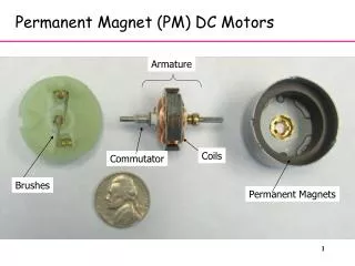
Download
1 / 26
260 likes | 561 Vues
Cryogenic Permanent Magnet Undulators. Finn O’Shea March 27, 2013 HBEB 2013, Puerto Rico. Outline. Motivation for shorter period technology As usual, it is money Prototype undulator has been tested Results are ‘ unsuprising ’ and that is a good thing!

E N D
Cryogenic Permanent Magnet Undulators Finn O’Shea March 27, 2013 HBEB 2013, Puerto Rico
Outline • Motivation for shorter period technology • As usual, it is money • Prototype undulator has been tested • Results are ‘unsuprising’ and that is a good thing! • Improving performance of cryogenic undulators through the use of rare-earth element poles – the DPU project • Cryogenic compatible magnetic materials lead to improved performance • Can we do the same with the pole material?
Motivation Researchers from many branches of science are using modern light sources to do a lot of cutting edge research LCLS accepts ¼ of proposals for beam time These machines are big (km) and expensive ($1/2 billion) Linacs are the really expensive part NGLS is being built through a mountain – real estate is getting more expensive
Where do short periods fit in? • “Moore’s Law” of radiation brightness is doubling every 10 months since the 1960s – this has come from bigger, more expensive facilities • Increased brightness does not lead to increased access unless the facilities become more common • The path to cheaper access is to increase the amount of radiation produced by each electron • Lots of beam lines on synchrotrons • Multiple beam lines at FELs: LCLS-II, NGLS, SwissFEL • Reduce the energy of the electrons required to produce the desired wavelengths
To make shorter periods… • The magnetic material needs to be very radiation resistant • In vacuum undulators have higher exposure because of the smaller gap and no vacuum chamber wall for protection • Cryogenically cooled magnets show a modest increase in remanent field and a massive increase in coercivity • They also show an increase in resistance to radiation induced demagnetization • Originally attributed to coercivity increase, more likely due to increase in heat capacity decreasing the effects of local heating • Rad damage is not well understood: • Radiation damage is reversible with remagnetization no structure change
Strategy to increase survivability • Use material that has maximum remanent field at room temperature • Limitation is ability to assemble the undulator • Cool as much as possible to get the highest possible magnetic field and largest coercivity/heat capacity • The clear choice is PrFeB • No SRT (NdFeB) • High remanent field (SmCo) Benabderrahmane, NIM A 669, 1 (2011).
Example of performance change LCLS Normal LCLS Low Charge/CPMU Energy = 4.5 GeV Charge = 250 fC Norm Emittance = 33 nm Saturation Length: 15 m Pulse Energy = 2.8 μJ Pulse Length = 0.5 fs B = 1.3 x 1036 ph/(s mm2 mrad2 0.1%) • Energy = 13.6 GeV • Charge = 250 pC • Norm Emittance = 0.4 μm • Saturation Length: 60 m • Pulse Energy = 1.5 mJ • Pulse Length = 100 fs • B = 2 x 1033 ph/(s mm2 mrad2 0.1%) PRSTAB 070702 (2010)
CPMU9 Testing of Cryogenic Permanent Magnet Undulator – 9 mm at the Next Linear Collider Test Accelerator
Cryogenic Permanent Magnet Undulator – 9 mm period • 9 mm period length • 20 period prototype • Compensated 1st integral • Working temp down to 11K • NLCTA experiment run at 43K
CPMU - II • Design process was iterative: use FEM and BIM codes to determine magnetically safe assembly and operating conditions as material is characterized. • Results in a 2D geometry with pieces that are strategically chamfered to reduce reverse fields
Measuring the field • Field is measured at cryogenic temps on a specially constructed measurement bench at HZ-Berlin • Bpeak=1.15 T (K=0.97)
Next Linear Collider Test Accelerator Facilities at NLCTA made it an excellent place to test the undulator using a scaled experiment at optical frequencies. Radiation bandwidth measurement Energy modulation measurement Confirmation of microbunching
Undulator Radiation Bandwidth • at NLCTA the bandwidth of the radiation should be dominated by the 5% bandwidth of the single electron radiation process
Laser seeding • 800 nm laser is used to seed the FEL mechanism • Laser is shorter than the electron beam, they are about the same transverse width • Leads to very 3D process • Energy modulation strength is function of distance along beam and radius • Genesis predicts: K = 0.97 K = 0.94
Observation of microbunching • Microbunching of electron beam causes coherent emission of transition radiation • CTR signal shows up as near field structure when laser is turned on • Null tests showed that this is likely forward CTR from OTR3 rather than backward CTR from OTR4, which is the screen that is imaged Laser on Laser off
Summary of Results • Bandwidth of the undulator radiation is dominated by the 5% interference bandwidth – consistent with expectations • Energy modulation is consistent with expected value from iFEL interaction • CTR appears when modulation is turned on – microbunching is occuring although scattering in OTR3 is spoiling the measurement
Rare-earth poles Dysprosium poles at RadiaBeam Technologies
Why replace CoFe? • Vanadium Permendur (49% Fe, 49% Co, 2% V) is an excellent pole material • Saturates at low applied field: μi~104 and Hsat<<0.1 T • Bsat = 2.35 T • The reason for replacing CoFe as the pole material of choice is to get higher saturation induction • Because we need to cool a CPMU anyway, what gains can be realized?
Rare-earth elements • Materials such as dysprosium, gadolinium and holmium show large sat. ind. at cryogenic temperatures • Dy -> 3.8 T (single crystal) • Single crystals are hard to grow and polycrystals are not useful • Secondary re-crystallization can be used to develop “texture”
Secondary Re-crystallization • Rolling then annealing exploits an energy advantage that results in the growth of the grains in-plane
Performance of textured Dy 100 μm thick foils CoFe • Competitive with CoFe if the applied field is • greater than ~0.10 T • Thinner foils should work even better • Non-linear nature and mixing of 1120 and • 1010 in different samples could be a problem
Short test undulator • Most poles are CoFe • One pole pair is replaced with Dy laminated poles • The field is measured while the undulator is cooled • BCoFe is compared to BDy
Results ~3%
Details • Effect is reproduced in Radia with the magnetization curves measured from one pole (destructive measurement via VSM) • Dy Pole position exposed it to larger applied fields than a typical pole • working point is above the Dy > CoFe point • Shows promise
Summary • Using shorter period undulators can: • Decrease the electron beam energy required to reach a given wavelength • Extend the reach of existing facilities • This can lead to cost savings and a potential increase in accessibility • A prototype short period cryogenic undulator has been built and tested in a successful scaled experiment at optical wavelengths • Rare-earth poles have the potential to outperform CoFe poles in undulators that can be cooled to the temperatures where they are ferromagnetic • Thank you!