Download
1 / 33
330 likes | 446 Vues
LANDING LIGHT One 600 Watt Landing Light mounted on Left Side beneath Nose Section. Light is powered by the No 1 DC Primary Bus via the Cct Bkrs marked “ LIGHTS, RETR LDG, CONT and PWR”

E N D
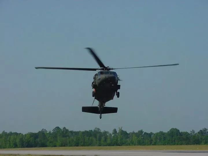
LANDING LIGHT • One 600 Watt Landing Light mounted on Left Side beneath Nose Section. • Light is powered by the No 1 DC Primary Bus via the Cct Bkrs marked “ LIGHTS, RETR LDG, CONT and PWR” • The Light can be extended or retracted, in the Fore/Aft Axis only, through 107 deg from the Stowed Position. The light will extend at 12 deg / sec and retract at 30 deg / sec. • The light must be fully extended or retracted by 130 KIAS. Once extended AS is limited to 180 KIAS. • The Light is controlled by a Dual Function Switch situated on both Collective Heads. To activate the light the switch is pushed downwards – an advisory light will then illuminate on the Caution/Advisory Panel. • To deactivate the switch is pushed again. To extend the light, the switch is pushed forward and to retract it is pushed backwards. Power will automatically be removed when the Light reaches either its forward or rearward extreme.
SEARCH LIGHT • One 150 Watt Searchlight mounted on bottom right of Nose Section. When the IR Filter is installed the maximum wattage Bulb to be used is 250 Watts. • Light is powered by the DC Essential Bus via the Cct Bkrs marked “ LIGHTS, CONTR PWR and SCH CONTR” • The Light can be extended or retracted through an arc of 120 deg from the stowed position. It can also be turned through 360 deg. The Light will extend at a rate of 12 deg/ sec. • Directional Control is accomplished by the 4 Way Searchlight Control Switch mounted on both Collective Heads. • The Light is turned on or off by a switch situated just above the Searchlight Control Switch on each Coll Head. This same switch controls the Brightness of the Searchlight provided the Output Switch below the Pilots Seat is in the NORM Position. • The light must be fully extended or retracted by 100 KIAS. Once extended AS is limited to 180 KIAS.
ANTI-COLLISION LIGHTS • Consists of Four Strobes in two separate units, one beneath the Aft Fuselage and one on top of the Aft Pylon Section. • The lights are powered by the No 2 AC Primary Bus via the Cct Bkr marked ‘LIGHTS, ANTI • The Lights are controlled by two switches on the upper console. One Switch selects either OFF, DAY (White strobes) or NIGHT (red strobes). The other switch selects Both, Upper of Lower Strobes. • When BOTH lights are selected the Upper Anti-Col will flash alternately with the Lower.
POSITION LIGHTS • Consists of three Normal Spectrum Lights and three IR Spectrum Lights. The IR Lights are co-located with the Normal Position Lights on the Left and Right Main Landing Gear Fairings as well as on top of the Tail Pylon. • The Normal Spectrum Lights are red on the left, green on the right and white on the tail. IR Spectrum lights are monotone. • The Normal Spectrum lights are powered by the No 2 DC Primary Bus via the Cct Bkr marked ‘NAV LTS’ whilst the IR lights are powered by the same Bus but via a Cct Bkr marked “IR LTS” • The Lights are controlled by three switches on the upper console. One Switch selects either OFF, DIM or BRIGHT, The second switch selects either STEADY or FLASH whilst the final switch selects either NORMAL or IR spectrum. The NORM/IR switch is also controls the Formation Lights.
POSITION LIGHTS (continued) Visible Spectrum Lights, Red on the left, Blue on the right, White on the Tail Pylon IR Position Light IR Position Light
FORMATION LIGHTS • Consist of 4 electroluminescent lights located on top of the main pylon cowling, tail drive shaft cover, and either side of the stabilator (see below) • Controlled by Rotary Switch on the overhead console and powered by No 2 AC Primary BUS via 2 cct bkrs marked ‘LIGHTS, FORM LV and HV’ • Position 1 corresponds to least intensity, Position 5 to most. • Formation Lights can be set to Infra Red via the toggle switch marked ‘NAV LTS, NORM and IR’ . This switch is also located on the overhead console. In the IR mode Position 1-4 corresponds to a uniform lighting intensity whilst Position 5 causes the lights to illuminate more brightly.
COCKPIT FLOOD LIGHTS • Consists of two Blue-Green and two White Flood Lights located on the Cockpit Flood Light Panel which in turn is located to the rear of the Overhead Console. • The Cockpit Flood Lights are controlled by a switch which is positioned between the two Flood Lights. • The Switch is a three position switch: OFF, WHITE and BLUE. • To place the switch in the ‘WHITE’ Position the switch itself must be pulled and held down whilst moving it. • The Cockpit Flood Lights are powered by the DC Essential Bus through a Cct Bkr marked ‘LIGHTS SEC PNL’
COCKPIT UTILITY LIGHTS • Consists of two Blue/Green / White Utility lights with coiled cords located on either side of the overhead console. • An additional light, called the auxiliary Utility Light is mounted on a flexible wand and is located on the right side of the Co-pilots seat. • The two overhead lights may be adjusted on their mountings or they may be removed and used portably. • All utility lights are controlled by a push button or Rheostat on the end of each light assembly. • The lens casing of each light is used to change from Blue/Green to White light. • The Cockpit Utility Lights are powered by the Battery Utility Bus through a Cct Bkr marked ‘UTIL LTS CKPT’. On acft post 97-26744, the lights are powered via the Battery Bus
CABIN DOME LIGHTS • Consists of three Dome lights in the Cabin area. • On/Off switch on the Over Head Console. Brightness control located on the left rear of the Pilots Seat. • Lights can be set to White or Blue. To place the switch in the ‘White’ Position the switch must be pulled and held whilst placing it in the White Position. • Lights are powered by the No 1 AC Primary Bus via a Cct Bkr marked ‘LIGHTS CABIN DOME’
OVERHEAD CONSOLE LEFT PANEL SWITCHES RIGHT PANEL SWITCHES
GLARE SHIELD LIGHTS • Consist of 6 lights installed in the instrument panel Glare Shield (see below). • Provide secondary lighting for the instrument panel • Controlled by Rotary Switch on the overhead console • Powered by the No 1 AC Primary Bus via a Cct Bkr marked ‘LIGHTS GLARE SHLD’
LIGHTED SWITCHES CONTROL • The lighted switches Rotary Dimmer controls the following lights: • CIS and HSI/VSI Mode Select Panels • Tail Wheel Locking Switch • AFCS Control Panel • No 1 and 2 Fuel Boost Pump Control Lights. • The Rotary Switch is only responsive when the Caution Advisory Panel is in the Dim Mode.
CO-PILOT FLIGHT INSTRUMENT LIGHTS • The Co-Pilots Flight Instrument Lighting is controlled by a Rotary Switch on the Left side of the Overhead Console. • Lighting is in the form of NVG Compatible Instruments Bezel Lights. • The Co-Pilots Flt Instruments Lights are powered by the No 1 AC Primary Bus via a Cct Bkr labelled ‘LIGHTS CPLT FLT’ • Both Radar Altimeters have lighting that are controlled by a RADALT Dimming Knob on the instrument Panel. These knobs are situated above each PDU and are only responsive when the Pilots Flight Lights Dimmer is moved from the ‘Off’ position.
PILOT FLIGHT INSTRUMENT LIGHTS • The Co-Pilots Flight Instrument Lighting is controlled by a Rotary Switch on the Left side of the Overhead Console. • Lighting is in the form of NVG Compatible Instruments Bezel Lights. • The Co-Pilots Flt Instruments Lights are powered by the No 2 AC Primary Bus via a Cct Bkr labelled ‘LIGHTS PLT FLT’ Radalt Dimming
UPPER CONSOLE LIGHTS • Upper Console Lights illuminate the Upper Console Lights and Instrument Markings. • The Upper Console Lights are powered by the No 1 AC Primary Bus via the “LIGHTS UPPER CSL” cct bkr.
LOWER CONSOLE LIGHTS • Lower Console Lights illuminate the Lower Console Instrument Markings as well as the Pilot and Co-Pilot Collective Heads. • The Lower Console Lights comprise of micro lights which illuminate the markings on the AFCS Panel, Misc Switch Panel, Boost Pump Control Panel, Retrans Control Panel, ESSS / AFMS Panel and Standby Compass. • Note: Many aircraft have no micro lights illuminating switch markings – the aux utility light should be used in this instance. • Avionics Lights either have no dimming or are controlled by integral dimming switches. • The ‘LIGHTED SWITCHES’ Dimmer control is for the AFCS, Tail Wheel Lock, CIS/HSI/VSI Mode Select and the No 1 / 2 Boost Pump control switches themselves. The Lower Console Dimmer does not control these (see Lighted Switches) • The Lower Console Lights are powered by the No 1 AC Primary Bus via the “LIGHTS LWR CSL” cct bkr.
NON FLIGHT INSTRUMENT LIGHTS • The Non Flight Instruments are all illuminated with the intensity of this lighting being controlled by a Rotary Switch on the Right side of the Overhead Console. • Non Flight Lights comprise of the CDU, Collective Heads and the Blade De-Ice Panel.
ADDITIONAL LIGHTING CONTROLS – DIMMER KNOBS • Two dimmer knobs above the Co-Pilots PDU control the intensity of the Caution Advisory and Master Warning Panel lights.
ADDITIONAL LIGHTING CONTROLS – PANEL KILL SWITCH • Each Cyclic Head contains a button which when pressed will cause all Caution Advisory and Master Warning Panel lights to extinguish. The lights can be restored by pressing the ‘Panel Lights’ button again.
ADDITIONAL LIGHTING CONTROLS – IR DIMMER SWITCH • The IR Searchlight contains a Transformer under the pilots seat which contains a Dimmer Switch. • The Switch can be placed in either the ‘NORM’ or ‘BYPASS’ position. • In the “NORM” position, which is all the way towards the centre console, the searchlight can be dimmed from 250 – 0 watts using the dimmer control switch on the Collective Head. • In the “BYPASS” mode the searchlight cannot be dimmed and will operate at 250 watts.
N 11. INTERIOR / EXTERIOR LIGHTING - SET • Standby Compass Light • All Instrument Lighting • All upper and lower console lighting • Collective Head Lighting • Cockpit Flood Lights • Cockpit Utility Lighting • Cabin Dome Lights • Landing Light – On prior to start until departed Lowe • Search light – as required • Anti-collision Lights – Night , Both (off for refuel) • Position Lights – Bright Steady, Flashing Bright when stationary for extended periods. • Formation Lights – Position 5