Download
1 / 43
450 likes | 717 Vues
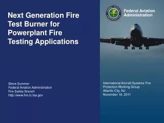
Development of a Next-Generation Burner for Testing Thermal Acoustic Insulation Burnthrough Resistance. Outline. Background Next Generation Burner Design Operational Parameters Proof of Concept Construction and Calibration of Multiple NexGen Burners

E N D
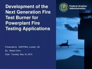
Development of a Next-Generation Burner for Testing Thermal Acoustic Insulation Burnthrough Resistance
Outline • Background • Next Generation Burner Design • Operational Parameters • Proof of Concept • Construction and Calibration of Multiple NexGen Burners • Comparative Testing of NexGen Burners at Various Locations
Background • Final Rule on thermal acoustic insulation burnthrough was issued in August 2003, but the compliance date was delayed until September 2009 • Airframe manufacturers had concerns with the availability and reliability of the specified test apparatus (Park DPL 3400 oil burner) • The Park oil burner was found to be out of production • Two different types of DPL 3400 were manufactured over the years, producing different flames
NexGen Burner Concept • Initial Concept: • Compressed air metered with a sonic nozzle (critical flow venturi) • Fuel provided by a pressurized fuel tank • Utilize the original Park draft tube components • Stator • Igniters • Nozzle • Turbulator • By using the same components and matching the air velocity and fuel flow rate, the overall character of the flame is unchanged
NexGen Burner Design Pressure Regulator Fuel Nozzle Cone Draft Tube Stator Muffler Igniters Housing Sonic Orifice Turbulator Cradle
Pressurized Fuel System Pressure Regulator (in the range of 0-150 psig) e.g., Bellofram Type 70 Pressure Regulator, 2-150 psig, max 250 psig inlet, approx $79 Solenoid or manual ball valve Solenoid or manual ball valve Needle valve to control venting Pressurized Air Inlet Fuel Fill Vent to lab or outdoors Compressed gas (from bottled Nitrogen or Air, or air compressor, if it is capable Vent Pressure Vessel (for example, McMaster-Carr p/n 1584K7, ASME-Code Vertical Pressure Tank W/O Top Plate, 15 Gallon Capacity, 12" Dia X 33" L, $278.69) or any suitable pressure vessel that can withstand pressures of around 150 psig. High pressure liquid level sight gauge (We use McMaster Carr p/n: 3706K23) Air/N2 @ ~120 psig Fuel This schematic is pretty basic. You can supplement this design with whatever instrumentation you would like to obtain the required data or to make for easier operation. Some examples would be a pressure transducer, remotely operated solenoid valves, fuel flow meter, etc. Fuel Outlet Nozzle 5.5 GPH 80 deg-PL Solenoid or manual ball valve Ice Bath H2O
Ice Bath Fuel Cooling Fuel in/out Air Cooling Water in/out Ice / Water Mixture Insulated Beverage Cooler 72 qt. capacity
Heat Exchange System Water Pump Condensate Separator McMaster-Carr p/n 43775K55 Cooler w/ice water Air From Compressor Burner Heat Exchanger McMaster-Carr p/n 3865K78 Blue = Water Lines Orange = Fuel Lines Black = Air Lines Fuel Tank
Burner Operational Parameters • Fuel • Type: JP8, Jet A or equivalent • Nozzle: Monarch 5.5 gph 80°PL • Pressure: 120 psig (±2 psig) • Temperature: 42°F (±10°F) • Flowrate: 6.0 gph (±0.3 gph) • Air • Pressure: 60 psig (±2 psig) • Temperature: 50°F (±10°F) • Mass Flow Rate: 66 SCFM (dictated by pressure)
Summary of Concept Phase • A burner can be fabricated from easily obtainable parts and materials • By replicating the input/output parameters of the Park oil burner, the concept burner could deliver a flame similar in character to that of the Park • The concept burner’s burnthrough performance was shown to be similar to the FAA Park oil burner, as well as several other “socket” type Park oil burners • A better method of measuring the burner performance is desired with a higher level of accuracy
Construction and Calibration of Multiple Burners • Objective • Construct 10 identical burners • Show reliability of performance from test to test (one burner) • Show repeatability of burner performance from burner to burner • Show reproducibility of burner performance at various locations • Procedure • Assemble and designate a burner (i.e., NG1, NG2, etc.) • Burner components are unique to each designated burner (stator, turbulator, cone, fuel rail, fuel nozzle, pressure regulator, muffler, sonic orifice) • Measure burner performance at FAATC lab (fuel flow, air flow, flame temperature, burnthrough times) • Package burner, ship to participating laboratory • Lab will perform same tests and compare results • If results are similar to those obtained at the FAATC, then burner is performing properly
NexGen Burner Distribution • Currently, NexGen burners are located at: • NG1: CEAT, Toulouse, France • NG2: FAATC • NG3: FAATC • NG4: Mexmil, Santa Ana, CA, USA • NG5: AIRBUS, Bremen, Germany • NG6: BOEING, Seattle, WA, USA • NG7: FAATC • NG8: JEHIER, Chemile, France • NG9: FAATC • NG10: FAATC • Parts for more burners will be ordered soon!
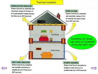
New Blanket Holder • Lightweight PAN (TexTech) materials have been found to have a high level of consistency with characteristic burnthrough times related to the material density (8579 or 8611) • These materials were also found to be greatly affected by the original blanket holder, the test rig that simulates the structure of an aircraft fuselage • A new sample holder was designed to increase the consistency of the burnthrough times in order to isolate the performance of the NexGen burners from all other effects
Picture Frame Blanket Holder INNER FRAME SUPPORTS OUTER FRAME
Frame Alignment 4” from cone face to blanket surface CL Centerline of picture frame (9.125”) is aligned with centerline of cone CL
Testing Material will typically shrink within 20 sec. from the top and the sides. The center portion, where the burnthrough is occurring, will not be affected by this.
Picture Frame Initial Results • High level of repeatability was observed • Identical results observed with the FAA Park and the NexGen • Much higher level of repeatability • Relative Standard Deviation decreased by a factor of 10
Summary of Results • Overall, the picture frame test method was useful in determining if burners are performing properly at different locations • The test method was found to be more repeatable and reproducible than when testing the same materials on the original blanket holder • Although this test method provides highly accurate results, it is in no means intended to replace the original test method • This testing method will not be required for calibrating NexGen burners; rather it can be used to ensure that a burner is not deviating from it’s original performance
Near-Future Work • Set up and administer a picture frame round robin test with all NexGen burner labs • Tight control • Burner input settings • Samples sent from FAA Tech Center • Conditioning of samples prior to testing • Lab test forms and data collection • Analyze data
Muffled Muffler • During seat burner trial and error testing, some reticulated foam was jammed into the muffler to see if it had an effect on creating a more uniform air stream • To our amazement it muted the sound of the sonic choke to almost as quiet as a Park burner • We then re-measured the burner exit velocity in the same manner as before with the Omega HH30 vane anemometer • The exit velocity was unchanged • Comparative picture frame testing is planned in order to verify the equivalence
Thermal Acoustic Insulation Blanket Comparative Testing • Boeing created 3 types of thermal acoustic insulation specimen samples: Material A, B, and C • Three tests worth of each material were created for each burner; therefore, each burner would run 9 tests total • Tests were run initially at Boeing then at the tech center on the FAA Park and FAA NG4 with Boeing personnel witnessing testing
Summary • A next-generation burner was developed for testing the burnthrough resistance of thermal acoustic insulation • The burner was constructed from readily available parts and materials • The burner performance was proven to be similar to that of the FAA Park • The burner was shown to perform similarly when moved from one laboratory to another • Multiple burners were constructed, and all were found to be in good agreement with each other and the FAA Park • A method was developed for quantifying the burnthrough performance of the NexGen burners • When testing thermal acoustic insulation blankets, the NexGen burners provided very similar results to that of the FAA Park