Troubleshooting Networking Problems
Troubleshooting Networking Problems. Understanding your school’s network. by Paul Clark – March 2009. Typical School Networks. Almost all schools use Ethernet Networks There’s Ethernet and then there’s Ethernet… (speed/switched/shared) There’s networks… and then there’s school networks….

Troubleshooting Networking Problems
E N D
Presentation Transcript
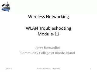
Troubleshooting Networking Problems Understanding your school’s network by Paul Clark – March 2009
Typical School Networks • Almost all schools use Ethernet Networks • There’s Ethernet and then there’s Ethernet… (speed/switched/shared) • There’s networks… • and then there’s school networks…
Defining the Network • Typically, each building at school would have a cabinet, but not necessarily • Cabinets are also called “distributors” • There’s usually a Campus Distributor (CD) and separate Building/Floor or Room Distributors (BDs) • The CD is normally the “centre” of your network with each of the BDs connected to the CD via “backbones” • Backbones can be copper or optic fibre cables
A Typical School Network Layout Copper Backbone fibre-optic Backbone Typical School Network CPC Server
Deciphering the Cabinet Optic Fibre Patch Panel contains connectors for fibre backbones to other cabinets Copper Patch Panel contains connectors that link to data outlets in various rooms. The numbers represent outlet numbers in rooms Optic Fibre Patch Leads connects fibre backbone(s) to Ethernet switches. These are usually orange in colour Copper (UTP) Patch Leadsconnect data outlets in rooms to the Ethernet switch(es). Copper leads can come in various colours See the Lights?? These indicate the switch is on, that computers are connected and that there is network activity from certain outlets when the lights flash. The numbers on the switch refer to switch ports, not outlet ports! Ethernet Switch(es)Your network cannot work without switches. They are the components that link your other switches, servers, computers, printers and other networkable devices together
Deciphering the Outlets Outlet Identification The outlets should all be numbered. The numbers refer to the copper patch panel in the cabinet. If there is a problem at a computer, it can be traced back to the patch panel, then to the switch port Learn About Your Network! Spend some time finding out how your network fits together. Draw a map! Where are the CD and the separate BDs? How are they linked? Where are the Outlets? And where and how many other Switches are there that are not in cabinets? UTP Outlets These outlets are in rooms where you need network access. In some newer schools the outlets can be used either for computers or for telephone handsets. If used for telephone, the outlet at the patch panel is patched into a PABX connection instead of into an Ethernet switch UTP Patch Leads These are the leads that connect to your network device. It could be a computer, a network printer or even another ethernet switch to allow for more computers to be connected within the room. If buying new leads, make sure they are CAT5E or CAT6 specification
What’s a Bridge Loop? • A switched network is in a “star” configuration radiating out to nodes (computers, printers, other switches) • Data is broadcast from the switches out to the nodes • A Bridge Loop is caused by one or more of the radiating connections being connected back into the switch • This “loop” in the network causes a “Broadcast storm” which can eventually cripple your network
You must never plug both ends of a single cable into the same switch! Where there are two switches there should only be one cable to link them! With multiple switches, you should link all switches with patch leads from one switch only! How is a Bridge Loop Caused? • All bridge loops are caused by human error! In a cabinet NOTE:Multiple copper or fibre backbone links can also cause bridge loops if plugged in incorrectly
How is a Bridge Loop Caused? In most schools, every port in a room has been patched to a switch in the cabinet, so if a student connects two ports in aroom, they will produce a bridge loop! Many schools place a small switch in each room to increase the number of computers they can connect in the room. Adding a single lead to connect two ports on the same switch and connecting that back to the network is a bridge loop! If two outlet ports are patched in the cabinet to the switch and those outlets are then connectedto the same switch in a classroom, you get a bridge loop! • REMEMBER! All bridge loops are caused by human error! In a classroom/office If you find a loose end of a cable, don’t just plug it in anywhere!
Spanning-Tree Protocol • Spanning Tree Protocol (STP) can be used to “ignore” bridge loops • But STP only works on managed switches. Most school have a mix of managed and “cheap” switches • If a bridge loop is made on a cheap switch, it will still bring down your managed network • Your best defence against bridge loops is understanding your network • I hope you do a little more now…