
鋰電池用負極材料
鋰電池用負極材料. 目前鋰二次電池之負極材料以石墨碳為主,依材料特性可分為三大類,分別為天然石墨 (Natural Graphite; NG) 、人造石墨 (Massive Artifical Graphite; MAG) 及中間相碳微球 (Mesocarbon Microbeads; MCMB) ,總計約占 95% 負極材料市場,而新型負極材料包括非石墨化無定形碳 (Glassy carbon) 、鈦酸鋰氧化物、矽基、錫基合金等。. 2010 年全球負極材料市占率. 全球負極材料需球量 (2008-2014).

鋰電池用負極材料
E N D
Presentation Transcript
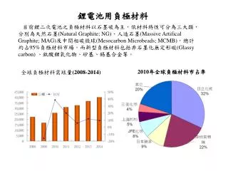
鋰電池用負極材料 目前鋰二次電池之負極材料以石墨碳為主,依材料特性可分為三大類,分別為天然石墨(Natural Graphite; NG)、人造石墨(Massive Artifical Graphite; MAG)及中間相碳微球(Mesocarbon Microbeads; MCMB),總計約占95%負極材料市場,而新型負極材料包括非石墨化無定形碳(Glassy carbon) 、鈦酸鋰氧化物、矽基、錫基合金等。 2010年全球負極材料市占率 全球負極材料需球量(2008-2014)
1. 電池負極材料市場呈現穩定成長,前兩大廠商日立化成及貝特瑞市佔率合計約占5成。根據IEK 2011/11預估,2011年全球負極材料需求量約30,941公噸,2008-2014 CAGR約10%,呈穩定成長。目前負極材料廠商集中度高,前兩大廠商為日立化成及深圳貝特瑞,2010年合計市佔率約占全球54%,皆擁有經濟規模優勢。 2. 根據研究機構報告,目前天然石墨、人造石墨及MCMB等石墨碳負極材料之應用比例約分別為60%、30%及9%,,一般3C用電池主要採用天然石墨,而動力電池則主要採用較高電容量的人造石墨及MCMB。目前日系動力電池廠商,如Sanyo及Panasonic偏好採用穩定度較佳的MCMB,而韓系及中國廠商則大部分採用成本較低之人造石墨。目前因人造石墨較MCMB生產設備成本低,且成本降低較易,將來與MCMB之競爭可期。
有關碳名詞的說明 Activated carbon (活性碳), also called activated charcoal(木炭), activated coal , is a form of carbon that has been processed to make it extremely porous and thus to have a very large surface area available for adsorption or chemical reactions. Glassy carbon, also called vitreous carbon, is a non-graphitizing carbon. Glassy carbon is widely used as an electrode material in electrochemistry. The structure of glassy carbon has long been a subject of debate. Early structural models assumed that both sp2- and sp3-bonded atoms were present, but it is now known that glassy carbon is 100% sp2. However, more recent research has suggested that glassy carbon has a fullerene-related structure.Note that glassy carbon should not be confused with amorphous carbon. This from IUPAC: "Glass-like carbon cannot be described as amorphous carbon because it consists of two-dimensional structural elements and does not exhibit ‘dangling’ bonds.“ Amorphous carbon has both sp2 and sp3 hybridized bonds present in the material. The properties of amorphous carbon films vary depending on the parameters used during deposition. One of the most common ways to characterize amorphous carbon is through the ratio sp2 to sp3 hybridized bonds present in the material. Graphite consists purely of sp2 hybridized bonds, whereas diamond consists purely of sp3 hybridized bonds. Carbon black is a material produced by the incomplete combustion of heavy petroleum products such as FCC tar(瀝青), coal tar, ethylene cracking tar, and a small amount from vegetable oil. Carbon black is a form of amorphous carbon that has a high surface-area-to-volume ratio, although its surface-area-to-volume ratio is low compared to that of activated carbon. Coke (焦炭)is the solid carbonaceous material derived from destructive distillation of low-ash, low-sulfur bituminous coal (煙煤). Volatile constituents of the coal—including water, coal-gas, and coal-tar—are driven off by baking in an airless furnace or oven at temperatures as high as 2,000oC, usually around 1000-1100 oC.
二次鋰電池負極材料碳的不同型態 Graphite Hard carbons Soft carbons Carbon nanotubes
LiC6 375mAh/g Relationships between reversible specific capacity and heat treatment temperature. Closed and open symbols are soft and hard carbons, respectively. XRD pattern of the coke sample heat treat at various temperature BSU basic structural unit Structural evolution of a graphitic carbon as a function of temperature Charge and discharge characteristics of natural graphite powder
Phase diagram of LixC6 obtained by an electrochemical method. in plane structure of stage-1 Li-GIC Stage structure of GIC 每一層碳 每兩層碳 每三層碳 每四層碳一層鋰 The stage structure changes successively from a higher to a lower stage during lithium intercalation. The dilute stage-1 (1’)denotes a phase where lithium ion is intercalated randomly within graphite and stage-2L denotes a liquid-like stage-2 phase that has no in-plane ordering.
量測值 計算值 Charge/discharge of petroleum-pitch-based pseudo-isotropic carbon (region D) (region C) Charge and discharge characteristic of MCMB heat-treated at 1800oC at 1st and 2nd cycles in 1MLiClO4/EC+DEC (region B) Charge/discharge of MCMB700 (region C) Variation of the reversible capacity of soft carbon with heat-treatment temperature.
An energy state model to explain voltage of region C soft carbon. Site A and B denote the intercalation and bonding sites. C H bonding site Li intercalation site
Improvement of natural graphite as a lithium-ion battery anodematerial, from raw flake to carbon-coated sphere Schematic views of the MCMB, shuttle-shaped and spherical natural graphite. Schematic views of the raw natural graphite flakes (upside) andshuttle-shaped natural graphite particles (downside) spread on the copper foil (current substrate).
1. Graphite is very sensitive towards electrolytes and caneasily be exfoliated in PC (propylene carbonate)-basedelectrolytes, which in turn decompose PC into propylene Gas. The organic propylene gas is likely to cause explosionunder some abuse conditions, which could be a potentialhazard for battery users. On the other hand, EC (ethylene carbonate)-based electrolytes are compatible with graphiteanode materials and appear as strong contenders with PCbasedones. Unfortunately, EC has a much higher melting point than PC (mpEC 39 uC; mpPC 249 uC), which will limit itsutilization at low temperatures. 2. Natural graphite is highly anisotropic. In other words, natural graphite flakes have wider dimensions in the parallel directions but thinner dimensions in the perpendicular direction to the basal planes. This kind of particle morphology has at least two shortcomings. Firstly, the natural graphite flakes are difficult to spread thinly and uniformly on the current collector substrate (copper foil). Secondly, natural graphite flakes coated on the copper foil generally demonstrate high orientation with the basal-plane surface exposed towards the current flow direction with edge-plane surface vertical to current flow. This type of alignment of graphite particles is not good for the rate capacity since Li+ intercalates into graphene layers via edge-plane surfaces. 3. To solve the first problem, we have applied a thermal vapor decomposition (TVD) technique to coat carbon onto natural graphite surfaces and to protect the natural graphite ‘‘core’’ from direct contact with the electrolytes. The electrochemical performance of natural graphite was greatly improved in both the EC and PC-based electrolytes after TVD carbon coating. As for the second problem, we have tried to change the particle shape of the natural graphite ‘‘core’’. The shuttle-shaped graphite particles demonstrate randomly stacked patterns when being spread with binder onto the copper foil to fabricate the electrode. However, Li+ intercalation will get sluggish at high current densities. This disadvantage mostly originates from the high orientation of graphene layers within each graphite ‘‘core’’ particle. If the natural graphite ‘‘core’’ could be rolled into a sphere, the problem of low rate capacity coming from high orientation might be solved.
All these curves demonstrate the typical plateau characteristic of the stage transformations between Li-graphite intercalation compounds. The irreversible capacity means the capacity difference between the charge and discharge curves. It can be obviously seen that the irreversible capacity corresponding to the ‘‘bare’’ natural graphite sample is bigger than the irreversible capacities of other carbon-coated graphite samples. All the charge-discharge curves corresponding to carbon coated samples almost overlap and there is little difference in the irreversible capacity values. Although 3 wt% is a very tiny amount, its influence on covering the surface of the spherical natural graphite ‘‘core’’ and preventing PC decomposition is comparable to the carbon-coating amount of 10 and 13 wt%. Comparison of the initial charge-discharge curves for the spherical natural graphite coated with different amounts carbon.
The superiority of spherical graphite coated with 3 wt% carbon over the highly-graphitized MCMB could be observed in the following respects. Firstly, the reversible capacity of the spherical graphite coated with 3 wt% carbon is higher than that of MCMB. Secondly, the irreversible capacity of the spherical graphite coated with 3 wt% carbon is smaller than that of MCMB, so the coulombic efficiency of the former sample is higher than that of the latter sample. Thirdly, the polarization between the charge and curves for the spherical graphite coated with 3 wt% carbon is lower than that corresponding to MCMB, which means that lithium-ion batteries using the former sample have a higher working voltage than the latter sample under the same conditions in the lithium-ion batteries. Comparison of the initial charge-discharge curves of MCMB and spherical natural graphite coated with 3 wt% The discharge capacity decrease with the increase of thickness of the electrode at a certain rate. The slope of each curve correlating discharge capacity with electrode thickness becomes more tilted as the thickness increases. Moreover, the curves of discharge capacity vs. electrode thickness shift downside as the rate becomes higher (the current density increases) for each sample. The curves corresponding to the spherical natural graphite coated with 3 wt% carbon lie over those for MCMB given the same rate. This fact implies that the spherical natural graphite coated with 3 wt% carbon could deliver more capacities than MCMB under the same conditions like current densities and electrode thickness. Comparison of the rate capacities of MCMB and spherical natural graphite coated with 3wt.% carbon (SNG).
SEI (Solid Electrolyte interface) film It is well known that the physicochemical nature of the cathode and anode materials determines the current and voltage outputs of the battery. The separator prevents the direct contact of the cathode and anode, and thus deters the short circuit of the battery. The electrolyte serves as the medium for the transfer of lithium ions and separates the transport of electrons from that of the lithium ions. To ensure the long cycling life of the battery, the electrolyte must be inert toward both cathode and anode materials during the operation of the battery. However, thermodynamically, such an electrolyte should be impossible considering the strongly oxidizing and reducing potencies of the cathode and anode materials employed in the high energy density LIBs. However, practical LIB systems have demonstrated that some nonaqueous electrolytes are apparently stable, enduring hundreds of charge–discharge cycles. To explain this surprising stability, it was suggested that in practical LIB systems, the electrode, which is in contact with the electrolyte solution, might be covered by a passivation layer. This layer consists of some insoluble products from the reaction of the electrode with the electrolyte and can kinetically prevent any sustained consumption of the electrolyte [3–5]. Because this passivation layer lies between the electrode and the electrolyte, and is conductive to ions but is nonconductive to electrons. It has generally become accepted that the SEI determines the battery’s electrochemical performance to a large extent.
First voltammetric cycle of artificial at low sweep rate 0.01 mV/s. Schematic illustration of the film forming mechanism via decomposition of Li(solv)yC.
Due to film forming a peak at potentials around 0.8 V versus Li/Li+ was observed during the first reduction. The reversibility of this peak was examined by cyclic voltammetry; in addition, the crystal expansion/contraction was checked by means of dilatometry. The results indicate that ternary solvated graphite-intercalation compounds (GICs) were formed at those potentials leading to drastic expansion of the graphite matrix (> 150%). These Li(EC)y1(DME)y2C,-GICs decompose and build up a protective layer on the graphite that prevents further solvent co-intercalation. The beneficial effect of EC-containing electrolytes on the stability of lithium—carbon anodes seems to be related to inorganic films formed via secondary chemical decomposition of electrochemically formed EC-GICs. The key-role of inorganic films is also demonstrated by the fact that inorganic additives, such as carbon dioxide, suppress the formation of solvated GICs. Furthermore, it can be seen that lithium-carbon negatives can even be operated in inorganic electrolytes such as SO2 and SOCl2. Series of consecutive voltammograms, each series taken with only one graphite electrode in EC-DME(50:50)/I MLiCIO4 with scanning rate 0.1 mV/s. There is a strong irreversible reduction ('filming') in sweep no. 4, the onset of this reduction is indicated in sweep no. 3, it is almost finished in sweep no. 5.
Reduction mechanism of EC on graphite proposed by Aurbach et. al.
Electrochemical impedance of Electrolyte/electrode interfaces of lithium-ion rechargeable batteries
(a) Scheme of three-dimensional complex plot of the impedance, (c) the instantaneous impedance obtained from the cross section. (b) the three-dimensional impedance shell and the cross section perpendicular to the time axis,
The real and imaginary parts of impedance in figure take the plus and minus values, respectively, indicating the capacitive behavior. The diameter of capacitive loop takes a large value at the early period of the first cycle charge and decreases abruptly with the charge time. The impedance after approximately 10000s in (a) shows two capacitive loops, and does not show apparent time variation. The impedance spectrum at the initial period of the first cycle discharge in (b) shows the capacitive loops, and the diameters of loops decrease with the discharge time.
Potential–capacity curves of the graphite electrode in EC/EMC (3:7 by volume) containing 1 M LiPF6 and 1 wt.% ethylene sulfite in the first cycle charge and the complex plane plots of the instantaneous impedance. The dc current density is 0.2mAcm−2.
Rct: charge transfer resistance Rsei: SEI film resistance From two resistances Rsei and Rct for graphite electrode, the change of negative electrode/electrolyte interface and the formation mechanism of SEI film were analyzed. The effect of the VC addition into the electrolyte solution was investigated, and it has been clarified that the VC helps to form the high quality SEI film at the early period of first cycle charge. On the other hand, the Rsei took a large value by the addition of ES, suggesting the formation of thick SEI film on the graphite electrode. And the irreversible capacity was 35% at the first cycle charge in EC/EMC+ 1 wt.% ES, which was larger value than that in the presence of VC.
電極片製備 • 陰極漿料製備 • 首先將LiFePO4、導電碳Super-P、導電碳KS-6以重量百分比85:5:5放入球磨罐內,以丙酮、氧化鋯溼球磨均勻混合粉末。再放到真空烘箱中以70℃蒸發掉丙酮,得到活性物質粉末。將黏著劑KYNAR HSV 900以重量比5%混合50c.cNMP溶劑,使用球磨罐均勻混合三十分鐘,再將活性物質粉末加入,混合三小時,得到陰極漿料。 • 陰極集片製作 • 裁切適當尺寸鋁箔,將鋁箔平鋪在塗佈台上。使用刮刀(塗佈厚度200μm)將漿料塗佈在鋁箔上,然後放入真空烘箱中,以120℃烘烤24小時去除極片上的NMP溶劑。冷卻後拿出,以自製的碾壓機碾壓極片三次,再放入極片切割器中切成尺寸為圓形(直徑1.2cm)極片,然後放入真空烘箱中,以120℃烘烤24小時去除極片上的水分。 • 陽極漿料配製 • 首先將MCMB、導電碳Super-P以重量比92:2放入到球磨罐中以丙酮溼球磨三小時後取出,放入到真空烘箱中以70℃蒸發丙酮得到陽級粉末。再把重量比6% KYNAR HSV 900混合NMP溶劑50c.c球磨半小時後再將陽極粉末放入球磨三小時,得到陽極漿料。 • 陽極極片塗佈 • 適當尺寸銅箔,將銅箔平鋪在塗佈台上,使用刮刀(塗佈厚度200μm)將漿料塗佈在銅箔上後,放入真空烘箱中。以120℃烘烤24小時,去除極片上的NMP溶劑,冷卻後拿出。以碾壓機碾壓極片三次,再切割比陰極極片大的圓形電極片,然後放入真空烘箱中,以120℃烘烤24小時去除極片上的水分
電池組裝過程: (a)放入LiFePO4極片,(b)蓋上隔離膜(薄膜電解質)滴數滴電解液,(c)再將經過電解液溼潤石墨電極片放入(d)疊上不銹鋼電流收極片,(e)疊上彈簧片,(f)放上上蓋,使用電池密合機密合。鈕扣電池編號CR2032A 。電解液EC/DEC/EMC 1:l:l (Vol%) lM LiPF6 + l% VC
Low voltage lithium-ion cells The comparison of the potential ranges of lithium intercalation electrodes.