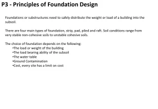
Foundation design
Foundation design. Present by Mr. Sieng PEOU Master science of geotechnical engineering Tel-011 874 974 email: sieng_2000@yahoo.fr. Type of foundation. Shallow foundation 1-Spread footing : support the load from building by column 2-Strip footing : support the load from building by walls


Foundation design
E N D
Presentation Transcript
Foundation design • Present by Mr. Sieng PEOU • Master science of geotechnical engineering • Tel-011 874 974 • email: sieng_2000@yahoo.fr
Type of foundation • Shallow foundation 1-Spread footing : support the load from building by column 2-Strip footing : support the load from building by walls 3-Mat foundation: combined all footing
Type of foundation • Deep foundation 1- End bearing pile : pile stand on rocks or very dense soils, so we have only end bearing capacity 2- Combined bearing pile : pile stand on normal soils, so we have end bearing capacity and skin friction 3- Floating pile : pile stand on very loose or very soft soil, so we have only skin friction
Spread footing Q B
Strip footing q B
End bearing pile Soft soil layer Pile Rock layer
Combined bearing pile Soft soil layer Pile Stiff soil layer
Floating pile Soft soil layer Pile
Bearing capacity for Shallow foundation • Type of failure 1-General shear failure for dense soil,we can use C & ffor design soils bearing capacity 2-Local shear failure for loose soil, we can use C’=2/3 C & f’=arctg(2/3tgf)for design soils bearing capacity 3-Punching shear failure for very loose soil,not recommended
General shear failure Q D Shear line
Local shear failure Q D Shear line
Ultimate bearing capacity qu qu s S S Settlement
Failure mechanisms and derivation of equations • A relatively undeformed wedge of soil below the foundation forms an active Rankine zone with angles (45º + f'/2). • The wedge pushes soil outwards, causing passive Rankine zones to form with angles (45º - f'/2). • The transition zones take the form of log spiral fans. • For purely cohesive soils (f = 0) the transition zones become circular for which Prandtl had shown in 1920 that the solution is qf = (2 + p) Cu = 5.14 Cu • This equation is based on a weightless soil. Therefore if the soil is non-cohesive (c=0) the bearing capacity depends on the surcharge qo. For a footing founded at depth D below the surface, the surcharge qo = gD. Normally for a shallow foundation (D<B), the shear strength of the soil between the surface and the founding depth D is neglected.
Semi-circular slip mechanism • Moment causing rotation = load x lever arm = [(q - qo) x B] x [½B] • Moment resisting rotation = shear strength x length of arc x lever arm = [Cu] x [p.B] x [B] • At failure these are equal: (q - qo ) x B x ½B = Cu x p.B x B • Net pressure (q - qo ) at failure = 2 p x Cu • This is an upper-bound solution.
Circular arc slip mechanism • Moment causing rotation = load x lever arm = [ (q - qo) x B ] x [B/2] • Moment resisting rotation = shear strength x length of arc x lever arm = [Cu] x [2a R] x [R] • At failure these are equal: (q - qo) x B x B/2 = Cu x 2 a R x R • Since R = B / sin a : (q - qo ) = Cu x 4a /(sin a)² • The worst case is when • tana=2a at a = 1.1656 rad = 66.8 deg • The net pressure (q - qo) at failure • =5.52 x Cu
Bearing capacity for strip footinggeneral equation After Terzaghi (1943) qd = CNc + s DNq +0.5 BN Nc = (Nq – 1 ) . Cotg Prandtl 1921 N = 2(Nq + 1)tg Caquot and Kerisel 1953 Vessic 1973
Bearing capacity for footingFrom TSA equationAfter Vessic (1973) qd = 5.14 Cu(1+0.2B/L) + s D Cu:Undrained cohesion B: Width of footing L: Length of footing
Bearing capacity for footingFrom TSA equationAfter Skemton (1951) qd = 5 Cu(1+0.2B/L)(1+0.2D/B) + s D D/B<2.5 Cu:Undrained cohesion B: Width of footing L: Length of footing D: Depth of footing
Bearing capacity for footingFrom TSA equationAfter Meyerhof (1951 to 1963) qd = 5.14 Cu(1+0.2B/L)(1+0.2D/B) + s D D/B<2.5 Cu:Undrained cohesion B: Width of footing L: Length of footing
Bearing capacity for footingFrom ESA equationAfter Vessic (1973) qd = s D Nq(1+B/L.tgf)+0.5gBNg(1-0.4B/L) f: Internal friction angle B: Width of footing L: Length of footing
Bearing capacity for footingFrom ESA equationAfter Meyerhof (1951 to 1963) qd = s D Nq.Sq.dq+0.5gBNgSgdg Sq=Sg=1+0.1KPB/L ; Kp= tg2(45+f/2) dq=dg=1+0.1Kp0.5D/B Nq the same Nq Terzaghi ; Ng=(Nq-1)tg(1.4f) f: Internal friction angle B: Width of footing L: Length of footing
Bearing capacity for footingFrom general equationAfter Meyerhof (1963) qd = C.Nc.Fcs.Fcd.Fci+s D Nq. Fqs.Fqd.Fqi +0.5gBNg Fgs.Fgd.Fgi qnet =C.Nc.Fcs.Fcd.Fci+s D (Nq-1). Fqs.Fqd.Fqi +0.5gBNg Fgs.Fgd.Fgi Nq by Reissner1924 ; Nc by Prandtl1921; Ng by Caquot and Kerisel 1953 and by Vessic 1973 f: Internal friction angle B: Width of footing L: Length of footing
Bearing factor • Shape factor by De Beer 1970 Fcs=1+B/L.Nq/Nc Fqs=1+B/L.tgf Fgs=1-0.4.B/L • Depth factor by Hansen 1970 Condition D/B<1 • Fcd=1+0.4D/B • Fqd=1+2.tgf(1-sinf)2D/B • Fgd=1
Bearing factor • Depth factor by Hansen 1970 Condition D/B>1 Fcd=1+0.4.arctg(D/B) Fqd=1+2.tgf(1-sinf)2.arctg(D/B) Fgd=1 • Inclined factor by Meyerhof 1963 Meyerhof and Hanna 1981 Fci=Fqi=(1-a/90)2 Fgi=(1-a/f)2
Bearing capacity of mat foundation • The gross ultimate bearing capacity of a mat foundation can be determined by the same equation used for shallow foundation. • A suitable factor of safety should be used to calculate the net allowable bearing capacity.For rafts on clay, the factor of safety should not be less than 3 under dead load and maximum live load.However, under the most extreme conditions,the factor of safety should be at least 1.75 to 2. For rafts constructed over sand,a factor of safety of 3 should normally be used.
Ultimate bearing capacity equation for mat foundation on saturated clay
Conventional Rigid Method Step1: Calculate the total column load Step2: Determine the pressure on the soil (q) below the mat at point A, B, C…by using the equation
Where A=BL Ix=(1/12)BL3 : moment of inertia about the X axis IY=(1/12)LB3 : moment of inertia about the Y axis Mx : moment of the column load about the X axis = Q.eY MY : moment of the column load about the Y axis = Q.ex
Step 3: Compare the values of the soil pressures determine in step 2 with the net allowable soil pressure to check if q<qall(net) Step 4: Divide the mat into several strips in X and Y direction. Let the width of any strip be B1. Step 5: Draw the shear and moment diagrams for each individual strip in X and Y direction. For example, take bottom strip in the X direction its average soil pressure can be given as:
qav=1/2(ql+qF) Where ql and qF soil pressures at point I and F The total soil reaction is equal to qavBB1 because the shear between the adjacent strips has not been taken into account. for this reason, the soil reaction and the column load need to be adjusted
eX and eY are the load eccentricities in the direction of the X and Y
Also, the column load modification factor is So the modified column load are FQi Now the shear and moment diagram for this strip can be drawn. this procedure can be repeated for all strips in the X and Y direction.
Step 6: determine depth of the mat d. This can be done by checking for diagonal tension shear near various column. According to ACI Code 318-95(section 11.122.1c). For critical section Where: -U : Factored column load (MN)=F -f : Reduction factor =0.85 -f’c : Compressive strength of concrete 28 days (MN/M2)
The unit of b0 and d in the preceding equation are in meters. The expression of b0 in term of d, which depends on the location of the column with respect to the plan of the mat, can be obtained from Figure 4.8c. Step 7: from the moment diagrams of all strips in a given direction (that is X or Y), obtain the maximum positive and negative moments per unit width M’=M/B1
Step8: Determine the areas of steel per unit width for positive and negative reinforcement in X and Y directions from the following equations. Where: -As: area of steel per unit width -fY :Yield stress of reinforcement in tension -Mu :Factored moment
Verify the stable of footing Q Qs Qf Qtotal=Q+Qf+Qs Q- load apply by column Qf –load of footing Qs –load of soil above footing B&L
Allowable bearing capacity • Net ultimate bearing capacity qnet=qd-gs.D • Net allowable bearing capacity qnetall=qnet/FS FS-Safety factor =3 • Gross allowable bearing capacity qall=qnetall+gs.D
Verify stable of footing We find value of B And verify the stable of footing from equation
When effect water table D1 Water level case I D D2 B d Water level case II
When effect water table 1-In case I if the water table is located so that 0<D1<D, so we will change the factor gs.D g.D1+D2(gsat-gw) Also value g in the last term of the equation has to be replaced by g’= (gsat-gw) 2-In case II for a water table located so 0<d<B value g in the last term of the equation has to be replaced by gcal= g’+d/B.(g-g’)
Stable of footing when effect inclined load qall>V/(BL) Tall>H Q H a D V=Q.Cos a H=Q.Sin a T=V.tg(2/3f)+2/3.C.B.L. Tall=T/1.5 T Q V B
When effect 0ne way bending moment We change B to B’ for calculate bearing capacity B’=B-2eB eB=MB/Q Q MB B
Verify stable of footing when effect one way bending moment When eB<B/6 Q MB
Verify stable of footing when effect one way bending moment When eB>B/6 Q MB Not recommended
Foundation with two way Eccentricity For calculate bearing capacity we have to change: B to B’=B-2eB L to L’=L-2eL A’=B’*L’ eB=MB/Q eL=ML/Q Q ML MB L B
Verify stable of footing when effect two way bending moment Qult= qu’.A’ Case eL/L>1/6 eB/B>1/6 B1=B(1.5-3eB/B) L1=L(1.5-3eL/L) B’=A’/L