Elasticity: Theory, Applications, and Numerics Explained
Understand elasticity basics, deformation modes, stress-strain concepts, and material failure mechanisms. Learn about elastic behavior of materials, linear vs. non-linear deformation, time-dependent effects, atomic models, and interatomic potentials.

Elasticity: Theory, Applications, and Numerics Explained
E N D
Presentation Transcript
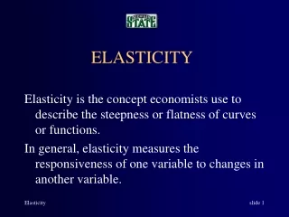
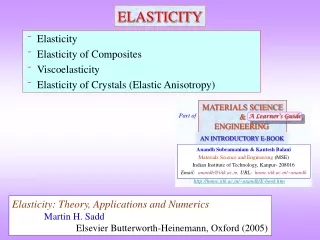
MATERIALS SCIENCE & ENGINEERING Part of A Learner’s Guide AN INTRODUCTORY E-BOOK Anandh Subramaniam & Kantesh Balani Materials Science and Engineering (MSE) Indian Institute of Technology, Kanpur- 208016 Email:anandh@iitk.ac.in, URL:home.iitk.ac.in/~anandh http://home.iitk.ac.in/~anandh/E-book.htm ELASTICITY • Elasticity • Elasticity of Composites • Viscoelasticity • Elasticity of Crystals (Elastic Anisotropy) Elasticity: Theory, Applications and Numerics Martin H. Sadd Elsevier Butterworth-Heinemann, Oxford (2005)
Revise modes of deformation, stress, strain and other basics (click here) before starting this chapter etc.
Let us start with some observations… • When you pull a rubber band and release it, the band regains it original length. • It is much more difficult (requires more load) to extend a metal wire as compared to a rubber ‘string’. • It is difficult to extend a straight metal wire; however, if it is coiled in the form of a spring, one gets considerable extensions easily. • A rubber string becomes brittle when dipped in liquid nitrogen and breaks, when one tries to extend the same. • A diver gets lift-off using the elastic energy stored in the diving board. If the diving board is too compliant, the diver cannot get sufficient lift-off. • A rim of metal is heated to expand the loop and then fitted around a wooden wheel (of say a bullock cart). On cooling of the rim it fits tightly around the wheel. Click here to know about all the mechanisms by which materials fail
Elasticity • Elastic deformation is reversible deformation- i.e. when load/forces/constraints are released the body returns to its original configuration (shape and size). • Elastic deformation can be caused by tension/compression or shear forces. • Usually in metals and ceramics elastic deformation is seen at low strains (less than ~10–3). At higher strains, in addition to elastic deformation we get plastic deformation. However, other materials can be stretched elastically to large strains (few 100%).So elastic deformation should not be assumed to be small deformation! • The elastic behaviour of metals and ceramics is usually linear (i.e. the stress strain curve is linear). Linear E.g. Al deformed at small strains Elasticity Non-linear E.g. deformation of an elastomer like rubber (or elastic deformation)
Time dependent aspects of elastic deformation • In normal elastic behaviour (e.g. when ‘small’ load is applied to a metal wire, causing a strain within elastic limit) it is assumed that the strain is appears ‘instantaneously’. • Similarly when load beyond the elastic limit is applied (in an uniaxial tension test: Slide 7 ), it is assumed that the plastic strain develops instantaneously. It is further assumed that the load is applied ‘quasi-statically’ (i.e. very slowly). • However, in some cases the elastic or plastic strain need not develop instantaneously. Elongation may take place at constant load with time. These effects are termed Anelasticity (for time dependent elastic deformation at constant load) and Viscoelasticity. Anelastic materials are a subset of viscoelastic materials. In anelastic materials the strain is fully recoverable and in dynamic loading, the stress-strain response depends on the frequency. Viscoelastic response depends on the rate of loading (strain rate). • Creep is one such phenomenon, where permanent deformation takes place at constant load (or stress). E.g. if sufficient weight is hung at the end of a lead wire at room temperature, it will elongate and finally fail. Recoverable Instantaneous Elastic Time dependent Anelasticity Deformation Instantaneous Plastic Viscoelasticity Time dependent Permanent
Atomic model for elasticity • At the atomic level elastic deformation takes place by the deformation of bonds (change in bond length or bond angle). • Let us consider the stretching of bonds (leading to elastic deformation). • Atoms in a solid feel an attractive force at larger atomic separations and feel a repulsive force (when electron clouds ‘overlap too much’) at shorter separations. (Of course, at very large separations there is no force felt). • The energy and the force (which is a gradient of the energy field) display functional behaviour as in the equations below*. This implies under a state of compressive stress the atoms ‘want to’ go apart and under tensile stress they want to come closer. Energy Force Repulsive Attractive A,B,m,n → constantsm > n The plots of these functions is shown in the next slide * This is one simple form of interatomic potentials (also called Lennard-Jones potential, wherein m = 12 and n = 6).
The plot of the inter-atomic potential and force functions show that at the equilibrium inter-atomic separation (r0) the potential energy of the system is a minimum and force experienced is zero. • In reality the atoms are undergoing thermal vibration about this equilibrium position. The amplitude of vibration increases with increasing temperature. Due to the slight left-right asymmetry about the minimum in the U-r plot, increased thermal vibration leads to an expansion of the crystal. Repulsive Repulsive r0 Force (F) → Potential energy (U) → r → r → Attractive r0 Attractive Equilibrium separation between atoms r0
Young’s modulus is the slope of the Force-Interatomic spacing curve (F-r curve), at the equilibrium interatomic separation (r0). I.e. it is the curvature of the energy-displacement (interatomic separation) plot. • In reality the Elastic modulus is 4th rank tensor (Eijkl) and the curve below captures one aspect of it. Young’s modulus (Y / E) Near r0 the red line (tangent to the F-r curve at r = r0)coincides with the blue line (F-r) curve • Young’s modulus is proportional to the –ve slope of the F-r curve at r = r0 r → Force → r0 For displacements around r0→ Force-displacement curve is approximately linear THE LINEAR ELASTIC REGION
Stress-strain curves in the elastic region • In metals and ceramics the elastic strains (i.e. the strains beyond which plastic deformation sets in or fracture takes place*) are very small (~103). As these strains are very small it does not matter if we use engineering stress-strain or true stress strain values (these concepts will be discussed later). The stress-strain plot is linear for such materials. • Polymers (with special reference to elastomers) shown non-linear stress-strain behaviour in the elastic region. Rotation of the long chain molecules around a C-C bond can cause tensile elongation. The elastic strains can be large in elastomers (some can even extend a few hundred percent), but the modulus (slope of the stress-strain plot) is very small. Additionally, the behaviour of elastomers in compression is different from that in tension. Tension Stress-strain curve for an elastomer Stress → T due to uncoilingof polymer chains C Due to efficient filling of space Strain → T C T > Compression * Brittle ceramics may show no plastic deformation and may fracture after elastic deformation.
Other elastic moduli • We have noted that elastic modulus is a 4th rank tensor (with 81 components in general in 3D). In normal materials this is a symmetric tensor (i.e. it is sufficient to consider one set of the off-diagonal terms). • In practice many of these components may be zero and additionally, many of them may have the same value (i.e. those surviving terms may not be independent). E.g. for a cubic crystal there are only 3 independent constants (in two index condensed notation these are E11, E12, E44). • For an isotropic material the number of independent constants is only 2. Typically these are chosen as E and (though in principle we could chose any other two as these moduli are interrelated for a isotropic material). More explained sooner. • In a polycrystal (say made of grains of cubic crystal), due to average over all orientations, the material behaves like an isotropic material. More about this discussed elsewhere. Mathematically the isotropic material properties can be obtained from single crystal properties by Voigt or Reuss averaging. In tensor notation • E → Young’s modulus • G → Shear modulus • K → Bulk modulus • → Poisson’s ratio
Relation between the elastic constants of an isotropic material • We have noted that for an isotropic material, the elastic properties are described by two independent elastic constants (typically, E & ). • The other elastic constants {like the bulk modulus (K) and the shear modulus (G or )} can be derived from these constants by standard formulae (e.g. below). List of elastic moduli for isotropic materials: Young’s modulus (Y, E), Poisson’s ratio (), Shear Modulus (G, ), Bulk modulus (K), Lamé’s constant (), P-wave modulus (M). • The relative magnitudes of these constants can be seen from the table below. • Similar to the stress-strain relation we saw before, other types of stresses can be related to the corresponding strain via the appropriate elastic moduli/constants (as below). Click here to know how isotropy can arise in a material
When a body is pulled (let us assume an isotropic body for now), it will elongate along the pulling direction and will contract along the orthogonal direction. The negative ratio of the transverse strain (t) to the longitudinal strain (t) is called the Poission’s ratio (). • In the equation below as B1 < B0, the term in square brackets ‘[]’ in the numerator is –ve and hence, Poission’s ratio is a positive quantity (for usual materials). I.e. usual materials shrink in the transverse direction, when they are pulled. • The value of E, G and for some common materials are in the table (Table-E). Zero and even negative Possion’s ratio have been reported in literature. The modulus of materials expected to be positive, i.e. the material resists deformation and stores energy in the deformed condition. However, structures and ‘material-structures’ can display negative stiffness (e.g. when a thin rod is pushed it will show negative stiffness during bulking observed in displacement control mode). Initial configuration is represented by ‘0’ in subscript
Elastic properties of some common materials T1 gives independent elastic constants of a cubic crystal. T2 lists elastic properties of selected isotropic materials. F1 shows a stress-strain plot in the elastic regime of select materials. F1 Room temperature data
Bonding and Elastic modulus • Materials with strong bonds have a deep potential energy well with a high curvature high elastic modulus. • Along the period of a periodic table the covalent character of the bond and its strength increase systematic increase in elastic modulus. • Down a period the covalent character of the bonding ↓ ↓ in Y. • On heating the elastic modulus decreases: on heating from 0 K → M.P there is a decrease of about 10-20% in modulus (i.e. Young’s modulus is not a sensitive function of T).
Anisotropy in the Elastic modulus What is meant by anisotropy (click here: Slide 13)? • In a crystal the interatomic and inter-planar distance varies with direction→ this aspect can be used to intuitively understand the origin of elastic anisotropy. We already know that linear and planar densities depend on the specific choice (i.e. the [100]CCP direction has different linear density as compared to the [111]CCP and similarly, the (100)CCP has a different planar density as compared to (111)CCP). • In a elastically anisotropic material, stretching along certain directions can lead to shearing. • Elastic anisotropy is especially pronounced in materials with ► two kinds of bonds, e.g. in graphite E [1010] = 950 GPa, E [0001] = 8 GPa ► Two kinds of ordering along two directions, e.g. in Decagonal QC E[100000]E[000001]
How to determine the elastic modulus? • The Young’s modulus (Y) of a isotropic material can be determined from the stress-strain diagram. But, this is not a very accurate method, as the machine compliance is in series with the specimen compliance. The slope of the stress-strain curve at any point is termed as the ‘tangent modulus’. In the initial part of the s-e curve this measures the Young’s modulus. Other kinds of mechanical tests can also be used for the measurement of ‘Y’. • A better method to measure ‘Y’ is using wave transmission (e.g. ultrasonic pulse echo transmission technique) in the material. This is best used for homogeneous, isotropic, non-dispersive material (wherein, the velocity of the wave does not change with frequency). Common polycrystalline metals, ceramics and inorganic glasses are best suited to this method. Soft plastics and rubber cannot be characterized by this method due to high dispersion, attenuation of sound wave and non-linear elastic properties. Porosity and other internal defects can affect the measurement. • The essence of the ultrasound technique is to determine the longitudinal and shear wave velocity of sound in the material (symbols: vl vs). ‘Y’ and Poisson’s ratio () can be determined using the formulae as below. Note again that it is not a good idea to calculate Young’s modulus for s-e plot • → density
Funda Check What is meant by anisotropy? • Anisotropy implies direction dependence of a given property. An isotropic material has the same value of a property along all directions. • Neumann’s principle states that symmetry of a property will be equal to or greater than the point group symmetry of the crystal. Cubic crystals (with 4/m 3 2/m) symmetry are isotropic with respect to optical properties. • Amorphous materials are isotropic. Polycrystalline materials with random orientation of grains are also isotropic. When such a polycrystalline material is plastically deformed, e.g. by rolling, the material develops crystallographic texture (preferential orientation of the grains) and this can lead to anisotropy. • Two important origins of anisotropy are: (i) crystalline, (ii) geometry of sample (shape). • Couple of effects of crystalline anisotropy: (i) if an electric field is applied along a direction, the current may flow along a different direction; (ii) if a body is pulled, it may shear in addition to being elongated.
Material dependent Elastic modulus Property Geometry dependent Stiffness Elastic modulus in design • In many applications the elastic properties of the material is the main one to be considered. However, other factors and properties should also be taken into account. • More than the modulus, it is the stiffness, which comes into focus as a design parameter. • Stiffness(as we have noted) of a ‘structure’ is its ability to resist elastic deformation (deflection) on loading → depends on the geometry of the component. Spring steel (e.g. high carbon steel with Si, Mn & Cr) will be characterized by its elastic modulus. In the form of the coil the spring (a structure with a certain geometry) shows more elongation for the same load and stiffness is the relevant property of the spring in design. • In many applications high modulus in conjunction with good ductility should be chosen (good ductility avoids catastrophic failure in case of accidental overloading) • Covalently bonded materials (e.g. diamond has a high E (1140 GPa)) in spite of their high modulus are rarely used in engineering applications as they are brittle (poor tolerance to cracks- for more on this refer to chapter on fracture). Ionic solids are also very brittle.
METALS • Metals are used in multiple engineering applications due to a combination of properties they possess: (i) reasonable elastic modulus, (ii) good ductility, (iii) ability to be alloyed to give good combination of properties, (iv) amenable to many types of fabrication techniques (casting, forging, extrusion, etc.), (v) good electrical and thermal conductivity, etc. The main issue with metals is often many of them have poor oxidation and corrosion resistance and not so good tolerance to high temperatures. • Metals of the First transition series posses a good combination of ductility & modulus (200 GPa). Second & third transition series have an even higher modulus, but their higher density is a shortcoming. POLYMERS • Polymers are light weight and have become universal. However, they have a low modulus dependent and cannot withstand high temperatures. They have a poor wear resistance as well. • The nature of secondary bonds (Van der Walls / hydrogen) is responsible for their low modulus. Further aspects which determine the modulus of polymers are: (i) presence of bulky side groups, (ii) branching in the chains Unbranched polyethylene E = 0.2 GPa, Polystyrene with large phenyl side group E = 3 GPa, 3D network polymer phenol formaldehyde E = 3-5 GPa(iii) Extent of cross-linking (more cross-linking give rise to higher stiffness).
Increasing the modulus of a material • The modulus of a metal can be increased by suitable alloying. • E is a structure (microstructure) insensitive property and this implies that grain size, dislocation density, etc. do not play an important role in determining the elastic modulus of a material. • One of the important strategies to increase the modulus of a material is by forming a hyrbrid/composite with an elastically ‘harder’ (stiffer) material. E.g. TiB2 is added to Fe to increase the modulus of Fe. COMPOSITES • A hard second phase (termed as reinforcement)can be added to a low E material to increase the modulus of the base material. The second phase can be in the form of particles, fibres, laminates, etc. • Typically the second phase though harder is brittle and the ductility is provided by the matrix. If the reinforcement cracks the propagation of the crack is arrested by the matrix. Particulate composite Aligned fiber composite Laminate composite Hybrids are designed to improve certain properties of monolithic materials Click here to know more about hybrids
Young’s modulus of a composite • The Young’s modulus of the composite is between that of the matrix and the reinforcement. • Let us consider two extreme cases.(A) Isostrain → the matrix and the reinforcement (say long fibres) are under identical strain.This is known as Voigt averaging.(B) Isostress → the matrix and fibre are under identical stress. This is known as Reuss averaging. • Let the composite be loaded in uniaxial tension and the volume fraction of the fibre be Vf (automatically the volume fraction of the matrix is Vm = (1 Vf)). Isostrain Voigt averaging This is like resistances in series These formulae are derived later Isostress This is like resistances in parallel Reuss averaging
The modulus of a real composite will lie between these two extremes (usually closer to isostrain). The modulus of the composite will depend on the shape of the reinforcement and the nature of the interface (e.g. in a long aligned fibre composite having a perfectly bonded interface with no slippage will lead to isostrain conditions. • Purely from a modulus perspective, a larger volume fraction will give a higher modulus; however, ductility and other considerations typically limit the volume fraction of reinforcement in a composite to about 30%. Voigt averaging • Under iso-strain conditions [m = f = c] • I.e. ~ resistances in series configuration • Under iso-stress conditions [m = f = c] • I.e. ~ resistances in parallel configuration • Usually not found in practice Reuss averaging Yf Isostrain Yc→ Isostress For a given fiber fraction f, the modulii of various conceivable composites lie between an upper bound given byisostrainconditionand a lower bound given by isostress condition Ym Volume fraction → Vf A B
Derivation of formulae Isostrain F Isostress Af Am L A F
Elasticity of Single Crystals and Anisotropy • For small stress, strain is proportional (linearly varies with) strain Hooke’s law. • The proportionality constants are 4th order (rank) tensors. The stiffness tensor is Eijkl or Cijkl. The compliance tensor is denoted as: Sijkl. • Number of components of Eijkl = Cijkl (or Sijkl) • in most general case (in practice the number of components reduces considerably): • 2D: 2222 = 16, (i = 1,2) • 3D: 3333 = 81, (i = 1,2,3) Tensor form Hooke’s law * Young’s modulus is an elastic constant and not an elastic modulus!
What does the existence of these Cijkl components physically mean? • If we apply just one component of stress (say 11), this in general will produce not only 11 but also other components of strain (which other components will depend on symmetry of the crystal- which we shall consider shortly). A glimpse of this we have already seen (in the topic on understanding stress and strain) if we pull a cylinder along y-direction, it will contract along the x-direction 11exists (apart from elongation in the y-direction 22). • But, this may not be the only other strain produced. 2D 3D • This implies that the body may shear also (12 = 21 exists). This occurs due to ‘anisotropy’ in the crystal. • So (in general) a bar: might shear if pulled (in addition to elongating) may twist if bent (in addition to bending) may bend if twisted (in addition to twisting).
We saw that a single stress component 11 may be related to many strains. • Similarly, many stress components may give rise to a single strain (11). 2D 3D There are 4 such equations (for each component ij) There are 9 such equations
No of independent components of Cijkl and Sijkl • The total number of expected components are: 2D: 2222 = 16, (i = 1,2); 3D: 3333 = 81 , (i = 1,2,3). But, not all of these are independent. • Cijkl = Cijlk (also, Sijkl = Sijlk) Cijkl = Cjikl (also, Sijkl = Sjikl) only 36 of the 81 components are independent (for even the most general crystal)*. • From energy arguments it can further be seen that: Cijkl = Cklij (also, Sijkl = Sklij)* of the 36 components only 21 survive (even for the crystal of the lowest symmetry i.e. triclinic crystal). • Given that crystals can have higher symmetry than the triclinic crystal, the number of independent components of Cijkl (or Sijkl) may be significantly reduced. • All cubic crystals (irrespective of their point group symmetry) have only 3 independent components of Cijkl (or Sijkl) these are C1111, C1122, C2323. • This is further reduced in the case of isotropic materials to 2 independent constants (C1111, C1122). Usually, these independent constants are written as E & . • Hence, for second rank tensor properties (like magnetic susceptibility, ij) cubic crystals are isotropic; but, not for forth rank tensor properties like Elastic Stiffness. * The reasoning is postponed for later.
The magnitude of anisotropy in cubic crystals is quantified using the Zener anisotropy factor (A) as defined in the equation below. • A value of ‘A’ of one (1) implies that the crystal is isotropic. A > 1 <111> direction stiffest Zener Anisotropy factory (A) A < 1 <100> direction stiffest