Download
1 / 40
420 likes | 640 Vues
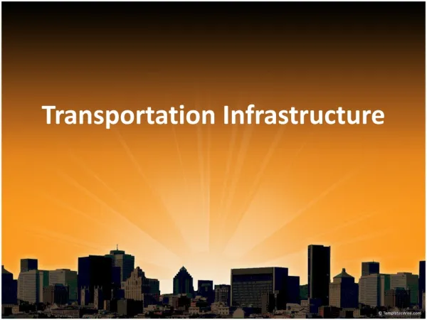
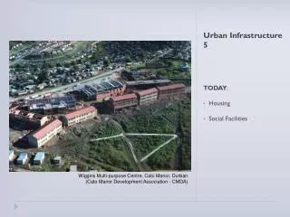
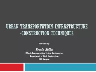
Urban Transportation Infrastructure -Construction Techniques. Presented by- Pravin Kolhe, MTech, Transportation System Engineering, Department of Civil Engineering, IIT Kanpur. Overview of presentation. Introduction Constraints during construction Planning for project Materials

E N D
Urban Transportation Infrastructure-Construction Techniques Presented by- Pravin Kolhe, MTech, Transportation System Engineering, Department of Civil Engineering, IIT Kanpur.
Overview of presentation • Introduction • Constraints during construction • Planning for project • Materials • Techniques for Urban Transportation Structure • Superstructure • Substructure PPT Downloaded from http://www.pravinkolhe.com/
1. Introduction • Urban transportation infrastructure involves large scale construction • There are various constraints. • Need of innovative techniques for timely completion. PPT Downloaded from http://www.pravinkolhe.com/
2. Constraints during construction • Space constraint • Time constraint • Utilities • Environment • Aesthetics • Safety • Economy PPT Downloaded from http://www.pravinkolhe.com/
2.1 Space constraint • Historical Places • Existing structures • Minimum disturbance to traffic • Photo.1. Space constraint • Photo: http://www.civil.skanska.com/skanska/templates/page.asp?id=3359 PPT Downloaded from http://www.pravinkolhe.com/
2.2 Time constraint • Construction of new infrastructure is normally taken up when existing infrastructure is not sufficient to fulfill the demand. • Urgent need to start and complete the construction • During the construction, the existing infrastructure is strained further. • So, timely completion of the project is important. PPT Downloaded from http://www.pravinkolhe.com/
2.3 Utilities • Infrastructure normally passes through densely populated area. • So, there are some utilities as • Water mains (Underground) • Sewer lines (Underground) • Telephone lines (underground or overhead) • Power supply lines. (overhead) • These utilities should be diverted, which is time consuming and costly affair. • Many times, the utilities are not known till the starting of work. PPT Downloaded from http://www.pravinkolhe.com/
2.4 Environment • Air and noise pollution • Due to slow moving vehicular traffic • Due to construction activity PPT Downloaded from http://www.pravinkolhe.com/
2.5 Aesthetics Photo 2. Aesthetics of urban transportation infrastructure PPT Downloaded from http://www.pravinkolhe.com/
2.6 Safety • Accidents causes loss of • Life • Property • Environment PPT Downloaded from http://www.pravinkolhe.com/
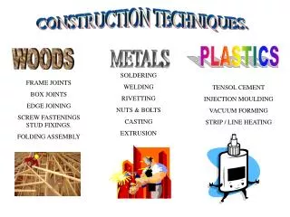
3 Materials • Preferred materials- • Bricks • Stones • Timber • Metals • Concrete • Composite PPT Downloaded from http://www.pravinkolhe.com/
3.1 Bricks • For small spans • Light Loads PPT Downloaded from http://www.pravinkolhe.com/
3.2 Stones • Old construction material • For small spans • Time consuming • Light load PPT Downloaded from http://www.pravinkolhe.com/
3.3 Timber • Temporary Bridges • Less span and less load PPT Downloaded from http://www.pravinkolhe.com/
3.4 Metal • Speedy construction • Large span • Heavy loads PPT Downloaded from http://www.pravinkolhe.com/
3.5 Concrete • Precast • Pre-stressed PPT Downloaded from http://www.pravinkolhe.com/
3.6 Composite Use of metal + Concrete PPT Downloaded from http://www.pravinkolhe.com/
4. Techniques for Construction • Elevated structures are divided it to- • Superstructure • Substructure Fig. 3. Components of elevated structures PPT Downloaded from http://www.pravinkolhe.com/
4.1 Techniques for Superstructure • Techniques- • Span-by-span construction with precast girder. • Precast post-tensioned segmental technique • Continuous units on ground supported staging • Central span by Cantilevering technique • Balanced cantilevering technique PPT Downloaded from http://www.pravinkolhe.com/
4.1.1 Span-by-span construction with precast girders • Most economical • Prestressed girders are lifted from casting yard and transported to site on trailers • At site they are lifted and placed on pier cap by cranes. • Deck slab is then casted over these girders. PPT Downloaded from http://www.pravinkolhe.com/
4.1.2 Precast post tensioned segmental technique • Simply supported post-tensioned units of 2~3 m with epoxy bonded joints. • For standardization of segments, cable profile is made horizontal in the middle span. Fig.5. Construction by Precast post-tensioned segmental technique PPT Downloaded from http://www.pravinkolhe.com/
4.1.3 Continuous units on ground supported staging • At crossing, central span is more. • So prestressed continuous units becomes obligatory. • In such case, central unit can be casted by staging by diverting traffic PPT Downloaded from http://www.pravinkolhe.com/
a) End spans are casted on staging b) Traffic diverted and central span is casted on staging c) Open to traffic. Fig 7. Construction of continuous unit on ground supported staging
4.1.4 Central span by cantilevering technique • End spans are casted on staging • Central span is casted by cantilevering. • When two cantilever meet, the stitch segment is casted. PPT Downloaded from http://www.pravinkolhe.com/
a) End spans are casted on staging b) Cantilevering construction started from ends c) Cantilevering construction completed from both ends. Fig 8. Construction of central span by cantilevering PPT Downloaded from http://www.pravinkolhe.com/
d) Stitch segment is casted e) Construction completed Fig 9. Construction of central span by cantilevering PPT Downloaded from http://www.pravinkolhe.com/
4.1.5 Balanced cantilevering technique • Only end portion of end span is casted on staging • Remaining end span and central span is casted by balanced cantilevering. • When two cantilever meet, the stitch segment is casted. PPT Downloaded from http://www.pravinkolhe.com/
a) End portion of end spans are casted on staging b) Cantilevering construction started from ends in both directions c) Cantilevering construction completed from both ends. Fig 10. Construction by balanced cantilevering PPT Downloaded from http://www.pravinkolhe.com/
d) Ground supported staging at end spans e) Stitch segment is casted f) Construction completed Fig 11. Construction by balanced cantilevering PPT Downloaded from http://www.pravinkolhe.com/
Fig. 12. Construction by balanced cantilevering PPT Downloaded from http://www.pravinkolhe.com/
4.2 Techniques for Substructure • Techniques- • Self supporting cutting. • Sheet piles • Diaphragm wall • Single cast-in-situ bored pile. • Driven casted pile • Group of piles. • Well foundation PPT Downloaded from http://www.pravinkolhe.com/
4.2.1 Self supporting cutting • For shallow depth and hard soil, soil cutting is possible at self supporting slopes. PPT Downloaded from http://www.pravinkolhe.com/
5.2.2 Using sheet pile • For higher depth &/or soft soil sheet pile are preferred. PPT Downloaded from http://www.pravinkolhe.com/
4.2.3 Using diaphragm wall • For deep cutting, diaphragm wall is most useful • These are installed prior to taking up the excavation work. • Generally, it is part of final structure PPT Downloaded from http://www.pravinkolhe.com/
4.2.4 Cast-in-situ bored pile • 150 - 600mm dia to 20m deep • As a rotary auger causes minimal vibration it is ideal for use next to buildings or underground services without destabilization. • Dewatering techniques can be used if water is present. Fig 13. Cast-in-situ bored pile PPT Downloaded from http://www.pravinkolhe.com/
4.2.5 Driven casted pile • 150mm - 600mm to 20m deep • Used on soft soils overlay. • Permanently steel cased piles are driven with an internal drop hammer. • Suitable reinforcement is then added and the casing filled with concrete. Fig 14. Driven casted pile PPT Downloaded from http://www.pravinkolhe.com/
4.2.6 Group of piles • Most of pile foundations consists not of a single pile, but of a group of piles, which act in the double role of reinforcing the soil, and also of carrying the applied load down to deeper, stronger soil strata. Fig 15. Group of piles PPT Downloaded from http://www.pravinkolhe.com/
4.2.7 Well foundation. • Used under very heavy loads to be carried by soft soil. Fig 16. Well foundation PPT Downloaded from http://www.pravinkolhe.com/
Contact: - Pravin Kolhe, Executive Engineer Water Resources Department, Government of Maharashtra Email:- pravinkolhe82@gmail.com www.pravinkolhe.com PPT downloaded from www.pravinkolhe.com
Thank you (c) Pravin Kolhe, 2006 http://www.pravinkolhe.com/