Wireless Communication Protocols and Technologies
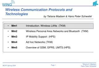
Wireless Communication Protocols and Technologies. by Tatiana Madsen & Hans Peter Schwefel. Mm1 Introduction. Wireless LANs (TKM) Mm2 Wireless Personal Area Networks and Bluetooth (TKM) Mm3 IP Mobility Support (HPS) Mm4 Ad hoc Networks (TKM)

Wireless Communication Protocols and Technologies
E N D
Presentation Transcript
Wireless Communication Protocols and Technologies by Tatiana Madsen & Hans Peter Schwefel • Mm1 Introduction. Wireless LANs (TKM) • Mm2 Wireless Personal Area Networks and Bluetooth (TKM) • Mm3 IP Mobility Support (HPS) • Mm4 Ad hoc Networks (TKM) • Mm5 Overview of GSM, GPRS, UMTS (HPS)
Course material • Download slides www.kom.auc.dk/~tatiana • Books • Jochen Schiller, ”Mobile Communications”, Addison-Wesley, 1st edition 2000, 2nd edition
Mobile vs Wireless user mobility: users communicate (wireless) “anytime, anywhere, with anyone” • Mobile vs Stationary • Wireless vs Wired Wireless Mobile device portability: devices can be connected anytime, anywhere to the network
Mobile vs Wireless Wireless vs. mobile Examples stationary computer notebook in a hotel wireless LANs in historic buildings Personal Digital Assistant (PDA)
Outline • Introduction - Historical perspectives • Properties of wireless medium • Basic MAC protocols for wireless communication • WLAN • IEEE 802.11 standard • Additional information • http://grouper.ieee.org/groups/802/11/ • B. Crow et al, “IEEE 802.11 Wireless Local Area Networks”, IEEE Comm. Magazine, September 1997
1860s J.C. Maxwell postulates electromagnetic waves 1880s H.R. Hertz provides proof of electromagnetic waves 1895 G. Marconi demonstrates wireless communication and applies for patent 1913 Establishment of marine radio telegraphy 1921 Detroit police conducts field trials with mobile radio 1946 Bell Lab. deploys first commercial mobile radio telephone system 1950 Microwave links are developed 1980s Wide deployment of analog cellular systems 1992 Introduction of 2nd generation digital cellular systems 1993 Introduction of multiservices capabilities in the 2nd generation systems 2000 Third generation cellular systems with multimedia capabilities are introduced 2003 Start of commercial deployment of 3rd generation systems Chronological list of events of wireless systems Source: B. Furht, Handbook of Internet and Multimedia Systems and Applications. IEEE Press, 1999
Key problems • Key problem - Path loss • Advent of the electron tube amplifier (de Forest, 1915) • Key problem – Thermal noise • Claude Shannon, ”A mathematical theory of communication”, 1949 • Advent of the Large Scale Integrated (LSI) circuits and Digital Signal Processing (DSP) • Key problem – The limited spectrum • Only one ”ether, unwanted interference between different users” • International Telecommunication Union (ITU) deals with these problems
Development of mobile communications Mobile Communications Networks Second Generation Third Generation First Generation • Analogue • Basic voice telephony • Low capacity • Limited local and regional coverage • E.g. NMT, AMPS, TACS, C-net • Digital: • Circuit switched • Voice plus basic data applications: • Fax • SMS (small message services) • Circuit-switched data • Low data speed • Regional coverage, with trans-national roaming • E.g. GSM, D-AMPS, PDC, IS 95 CDMA • Digital: • Packet and circuit switched • Advanced data — i.e. multimedia applications • Fast data access • Global coverage • E.g. UMTS (WCDMA, TD/CDMA), IMT-2000 Wireless data already be introduced in second generation mobile Source: “Mobile data feels pressure from the need for speed”, Network News, 2 June 1998 (CAP Gemini, September 1999)
Possible UMTS extension for high speed data access with roaming capability Mobility & Range High SpeedVehicularRural GSM VehicularUrban UMTS Fixed urban IEEE 802.11a/b (WLAN), Hiperlan2,MMAC Pedestrian DECT BRAN Indoor B-PAN PAN Personal Area Bluetooth 1000 Mb/s 0.5 10 2 20 155 Total data rate per cell
Germany Greece Spain Belgium France Netherlands Great Britain Switzerland Ireland Austria Portugal Luxemburg Italy Denmark Norway Sweden Finland 0 10 20 30 40 50 60 Mobile phones per 100 people 1999 2002: 50-70% penetration in Western Europe
700 600 500 Americas Europe 400 Japan 300 others total 200 100 0 1996 1997 1998 1999 2000 2001 Worldwide wireless subscribers http://www.3g.co.uk
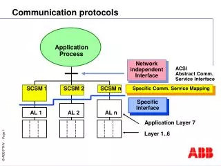
Network Network Simple reference model Application Application Transport Transport Network Network Data Link Data Link Data Link Data Link Physical Physical Physical Physical Medium Radio
Signal propagation ranges • Transmission range • communication possible • low error rate • Detection range • detection of the signal possible • no communication possible • Interference range • signal may not be detected • signal adds to the background noise sender transmission distance detection interference Broadcast nature of channel
Signal propagation • Propagation in free space always like light (straight line) • Receiving power proportional to 1/d² (d = distance between sender and receiver) • Receiving power additionally influenced by • fading (frequency dependent) • shadowing • reflection at large obstacles • refraction depending on the density of a medium • scattering at small obstacles • diffraction at edges refraction shadowing reflection scattering diffraction
multipath pulses LOS pulses signal at sender signal at receiver Multipath propagation • Signal can take many different paths between sender and receiver due to reflection, scattering, diffraction • Time dispersion: signal is dispersed over time interference with “neighbor” symbols, Inter Symbol Interference (ISI) • The signal reaches a receiver directly and phase shifted distorted signal depending on the phases of the different parts
Wireless medium • Time varying channel • Radio signals propagate according to reflection, diffraction and scattering • The received signal power attenuates as for free space • Multipath propagation • Fading • Burst channel errors • Broadcast nature of channel • Half-duplex operation
Wireless networks in comparison to fixed networks • Higher loss-rates due to interference • emissions of, e.g., engines, lightning • Restrictive regulations of frequencies • frequencies have to be coordinated, useful frequencies are almost all occupied • Low transmission rates • Higher delays, higher jitter • Lower security, simpler active attacking • radio interface accessible for everyone, base station can be simulated, thus attracting calls from mobile phones • Always shared medium • secure access mechanisms important
A B C Hidden and exposed terminals • Hidden terminals • A sends to B, C cannot receive A • C wants to send to B, C senses a “free” medium • collision at B, A cannot receive the collision • A is “hidden” for C • Exposed terminals • B sends to A, C wants to send to another terminal (not A or B) • C has to wait, CS signals a medium in use • but A is outside the radio range of C, therefore waiting is not necessary • C is “exposed” to B
A B C Near and far terminals • Terminals A and B send, C receives • signal strength decreases proportional to the square of the distance • the signal of terminal B therefore drowns out A’s signal • C cannot receive A • If C for example was an arbiter for sending rights, terminal B would drown out terminal A already on the physical layer • Also severe problem for CDMA-networks - precise power control needed!
MAC Protocols Fixed assignment Demand assignment Random assignment s-ALOHA TDMA CDMA ALOHA GAMA Token FDMA FAMA CSMA Polling Classification of Wireless MAC protocols
Access methods SDMA/FDMA/TDMA • SDMA (Space Division Multiple Access) • segment space into sectors, use directed antennas • cell structure • FDMA (Frequency Division Multiple Access) • assign a certain frequency to a transmission channel between a sender and a receiver • permanent (e.g., radio broadcast), slow hopping (e.g., GSM), fast hopping (FHSS, Frequency Hopping Spread Spectrum) • TDMA (Time Division Multiple Access) • assign the fixed sending frequency to a transmission channel between a sender and a receiver for a certain amount of time
User 1 packet 1 packet 1 rescheduled packet 1 packet 2 packet 2 rescheduled User 2 successful transmission collision successful transmission successful transmission Base station time t0 t0+tp1 t1 t1+tp2 Random Access - Aloha • Unslotted Aloha • Slotted Aloha
Carrier Sense Multiple Access (CSMA) • Aloha schemes “impolite” behavior • CSMA “listen before talk” • Process of listening to the channel is not demanding • Carrier sensing does not relieve us from collisions • Variations of CSMA are due to behavior of users when the channel is busy • Non-persistent • 1-persistent • p-persistent
Non-persistent CSMA • If the channel is busy, a terminal refrains from transmitting a packet and behaves exactly as if the packet collided. • a - vulnerable period a a a T
1-persistent CSMA • Non-persistent CSMA: there are situations when the channel is idle, although one or more users have packets to transmit. • 1-persistent: if the channel is idle, the user waits and transmits as soon as the channel becomes idle.
Slotted systems • The wireless channel is said to be slotted if transmission attempts can take place at discrete instance in time. • A slotted system requires network-wide time synchronization • in centralized network BS is used as a reference • in distributed networks it is more difficult • slotted non-persistent and 1-persistent CSMA
CSMA with Collision Detection • Whenever the transmission of two or more packets overlap in time, all packets are lost and must be retransmitted • In some local area networks (such as Ethernet) users can detect interference among several transmission (including their own) while transmission is in progress • If a collision is detected during transmission, the transmission is aborted. • Consensus reenforcement procedure • Transmission period in the case of collision:
Collision detection in radio systems • Wire: transmitted and received signals are of the same order of magnitude • Wireless: the received signal is considerably weak compared with the transmitted • in radio systems CD is usually not implemented • ACK is required
Characteristics of wireless LANs • Advantages • very flexible within the reception area • Ad-hoc networks without previous planning possible • (almost) no wiring difficulties (e.g. historic buildings, firewalls) • more robust against disasters like, e.g., earthquakes, fire • Disadvantages - users expect the same services and capabilities • typically very low bandwidth compared to wired networks (1-10 Mbit/s) • many proprietary solutions, especially for higher bit-rates, standards take their time (e.g. IEEE 802.11) • products have to follow many national restrictions if working wireless, it takes a vary long time to establish global solutions like
Design goals for wireless LANs • global, seamless operation • low power for battery use • no special permissions or licenses needed to use the LAN • robust transmission technology • simplified spontaneous cooperation at meetings • easy to use for everyone, simple management • protection of investment in wired networks • security (no one should be able to read my data), privacy (no one should be able to collect user profiles), safety (low radiation) • existing applications should work
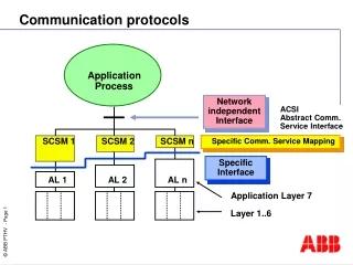
access point application application TCP TCP IP IP LLC LLC LLC 802.11 MAC 802.11 MAC 802.3 MAC 802.3 MAC 802.11 PHY 802.11 PHY 802.3 PHY 802.3 PHY IEEE 802.11 standard IEEE=Institute of Electrical and Electronics Engineers • 802.3 Ethernet • 802.5 Token ring • 802.11 WLAN • 802.15 WPAN • Standards specify PHY and MAC, but offers the same interface to higher layers to maintain interoperability
PLCP Physical Layer Convergence Protocol clear channel assessment signal (carrier sense) PMD Physical Medium Dependent sublayer modulation, coding of signals PHY Management channel selection Station Management coordination of all management functions MAC access mechanisms, fragmentation, encryption MAC Management association, re-association of a station to an AP, roaming authentication, encryption synchronization, power management 802.11 - Layers and functions Station Management LLC DLC MAC MAC Management PLCP PHY Management PHY PMD
Portal Distribution System System architecture 802.11 - Architecture of an infrastructure network 802.11 LAN 802.x LAN • Station (STA) • terminal with access mechanisms to the wireless medium and radio contact to the access point • Basic Service Set (BSS) • group of stations using the same radio frequency • Access Point • station integrated into the wireless LAN and the distribution system • Portal • bridge to other (wired) networks • Distribution System • interconnection network to form one logical network (EES: Extended Service Set) based on several BSS STA1 BSS1 Access Point Access Point ESS BSS2 STA2 STA3 802.11 LAN
802.11 - Architecture of an ad-hoc network 802.11 LAN • Direct communication within a limited range • Station (STA):terminal with access mechanisms to the wireless medium • Independent Basic Service Set (IBSS):group of stations using the same radio frequency STA1 STA3 IBSS1 STA2 IBSS2 STA5 STA4 802.11 LAN
802.11 - Physical layer • 3 versions: 2 radio (typ. 2.4 GHz), 1 IR • data rates 1 or 2 Mbit/s • FHSS (Frequency Hopping Spread Spectrum) • separate different networks by using different hopping sequences • 79 hopping channels; 3 different sets with 26 hopping sequences per set • DSSS (Direct Sequence Spread Spectrum) • method using separation by code • preamble and header of a frame is always transmitted with 1 Mbit/s, rest of transmission 1 or 2 Mbit/s • chipping sequence: +1, -1, +1, +1, -1, +1, +1, +1, -1, -1, -1 (Barker code) • max. radiated power 1 W (USA), 100 mW (EU), min. 1mW • Infrared • 850-950 nm, diffuse light, typ. 10 m range, indoor • carrier detection, synchronization
IEEE 802.11 MAC • 802.11 supports 2 different fundamental MAC schemes: • The Distributed Coordination Function (DCF): all users have to contend for accessing the channel. This is an implementation of ad hoc networks. • The Point Coordination Function (PCF): is based on polling and is performed by an AP inside the BSS. In the IEEE 802.11 implementation of PCF is optionally. • The PCF is required to coexist with the DCF: when the PCF is available in a network, there still is a portion of the time allocated to the DCF.
Access methods • DFWMAC-DCF CSMA/CA (mandatory) – basic access method • collision avoidance via randomized „back-off“ mechanism • minimum distance between consecutive packets • ACK packet for acknowledgements (not for broadcasts) • DFWMAC-DCF w/ RTS/CTS (optional) – handshaking access method • avoids hidden terminal problem • DFWMAC- PCF (optional) • access point polls terminals according to a list
Traffic services • Asynchronous Data Service (mandatory) • exchange of data packets based on “best-effort” • support of broadcast and multicast • Time-Bounded Service (optional) • implemented using PCF (Point Coordination Function)
Carrier Sensing • Carrier sensing is performed at both the air interface, reffered to as physical carrier sensing, and at the MAC sublayer, reffered to as virtual carrier sensing. • Physical c.s. detects activity in the channel via relative signal strength from other sources • Virtual c.s. - from header information of frames. The duration field indicates the amount of time (in microseconds) after the end of the present frame the channel will be utilized. This time is used to adjust network allocation vector (NAV). • The channel is marked busy if one of the c.s. indicate the channel is busy.
Priorities • Priorities • priority access to the channel is controlled through the use of interframe space - mandatory periods of idle time. • SIFS (Short Inter Frame Spacing) • highest priority, for ACK, CTS, polling response • PIFS (PCF IFS) • medium priority, for time-bounded service using PCF • DIFS (DCF, Distributed Coordination Function IFS) • lowest priority, for asynchronous data service DIFS DIFS PIFS SIFS medium busy contention next frame t direct access if medium is free DIFS
Random backoff time mechanism • After DIFS period, a station computes a random backoff time • time is slotted to Slot_Time - to define IFS and backoff time • the r.b. Is an integer value that corresponds to a number of time slots • initially it is 0-7 • if the timer reached zero and medium is idle --> transmit • if the medium becomes busy --> freeze the timer • if collision --> new backoff time 0-15 • the idle period after DIFS is called contention window • this method promotes fairness
802.11 - CSMA/CA basic access method contention window (randomized back-offmechanism) DIFS DIFS • station ready to send starts sensing the medium (Carrier Sense based on CCA, Clear Channel Assessment) • if the medium is free for the duration of an Inter-Frame Space (IFS), the station can start sending (IFS depends on service type) • if the medium is busy, the station has to wait for a free IFS, then the station must additionally wait a random back-off time (collision avoidance, multiple of slot-time) • if another station occupies the medium during the back-off time of the station, the back-off timer stops (fairness) medium busy next frame t direct access if medium is free DIFS slot time
DFWMAC • Network Allocation Vector (NAV) is time field that indicates the duration of the current transmission • Backoff procedure is used to randomized access to the channel backoff DIFS Medium busy RTS data sender SIFS SIFS SIFS CTS ACK receiver DIFS NAV (RTS) other stations NAV (CTS) t defer access
Trade-offs with RTS/CTS • Collisons are avoided • Hidden station problem is solved • Bandwidth reduction • Not with multicast and broadcast Usage With large frames When collisions are likely
Fragmentation • Large frames handed down from the LLC to the MAC may require fragmentation to increase transmission reliability • Fragmentation_threshold • the channel is not released until the whole frame is transmitted successfully or the source fails to receive ACK for a fragment. DIFS RTS frag1 frag2 sender SIFS SIFS SIFS SIFS SIFS CTS ACK1 ACK2 receiver NAV (RTS) NAV (CTS) DIFS NAV (frag1) data other stations NAV (ACK1) t contention
t0 t1 SuperFrame medium busy PIFS SIFS SIFS D1 D2 point coordinator SIFS SIFS U1 U2 wireless stations stations‘ NAV NAV DFWMAC-PCF • The beginning of a super frame is indicated by a beacon transmitted by AP. (synchronization) • the minimum duration of PCF period is time required to send 2 frames + overhead + PCF-end-frame • the maximum duration - time must be allotted for at least one frame to be transmitted during DCF period
t2 t3 t4 PIFS SIFS D3 D4 CFend point coordinator SIFS U4 wireless stations stations‘ NAV NAV contention free period t contention period DFWMAC-PCF