Prototype HFT readout system
Prototype HFT readout system. Telescope prototype based on three Mimostar2 chips. Outline. Motivation for the prototype telescope Realization of the telescope System architecture Hardware Firmware Calibration results for MimoStar2 chips Test results with 1.5 GeV electrons

Prototype HFT readout system
E N D
Presentation Transcript
Prototype HFT readout system Telescope prototype based on three Mimostar2 chips
Outline • Motivation for the prototype telescope • Realization of the telescope • System architecture • Hardware • Firmware • Calibration results for MimoStar2 chips • Test results with 1.5 GeV electrons • Full-frame readout • Normal readout mode (data after cluster-finder)
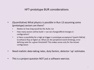
Motivation for the telescope • The telescope is a small prototype and contains all elements easily scalable to meet the requirements of the HFT test functionality of a prototype MIMOSTAR2 detector in the environment at STAR 2006-2007: • Charged particle environment near the interaction region in STAR. • The noise environment in the area in which we expect to put the final HFT. • Performance of the MIMOSTAR2 sensors. • Performance of our cluster finding algorithm. • Performance of our hardware / firmware as a system. • Functionality of our tested interfaces to the other STAR subsystems.
Realization of the telescope MimoStar2 chips on kapton cables MOTHER BOARD DAUGHTER CARD Control PC (Win) STRATIX Acquisition Server (Linux) RORC SIU
MimoStar2 chips on kapton cables MOTHER BOARD DAUGHTER CARD Control PC (Win) STRATIX Acquisition Server (Linux) RORC SIU Realization of the telescope (1) CDS, sorting, CF (2) TCD trigger Continuous MimoStar2 readout (3) Building event (0) Data acquisition complex Hardware and Firmware development (4) Formatted Event (5) Transfer data for this event
analog 3 MimoStar2 chips as TELESCOPE 1st pixel marker Power, clk, sync, jtag Hardware – telescope head TELESCOPE HEAD Kapton cable: • 2 Cu layers • Thickness 25μm (kapton only) • DONE & UNDER TEST
Hardware components I Mother board • Trigger interface to TCD • Latch up protection on all power supplies • Remote FPGA programming Daughter Card • 50 MHz 12bit ADCs with serial readout • SRAM • Accept and respond to triggers • Data resorter (because sub-arrays of MimoStar2 are multiplexed) • CDS • Cluster finder • Cluster FIFO • Event builder • DONE & WORKING Daughter card form the previous stage of development – in the future probably integrated into MB
Hardware components II STRATIX development board • DDL control interface • JTAG config for MimoStar2 ALICE DDL-RORC system • Optic fiber link to the remote DAQ PC • Half duplex connection • Part of the DAQ1000 Upgrade • DONE & WORKING
Firmware – overview • scalable • DONE & WORKING
Firmware - Cluster Finder • on line cluster finding will allow to reduce data flow at HFT by about three orders of magnitude 320 pixels deep shift register • DONE & WORKING
Firmware – Event builder • Each Trigger enables an empty Event FIFO for 1 frame (204,800 clocks = 4ms) with an offset to the enable that aligns the event start time with the location of the first pixel in the event. • Each event FIFO is a separate trigger event stream and can be enabled independently. This allows events to be triggered at ~1 ms intervals with our 4 ms latency. • Each sector event FIFO is emptied by the SIU at the end of it’s triggered frame. • DONE & WORKING DATA FORMAT header includes: • 4 byte start tag • 12 bit Token (from TCD) • Mimostar position on ladder
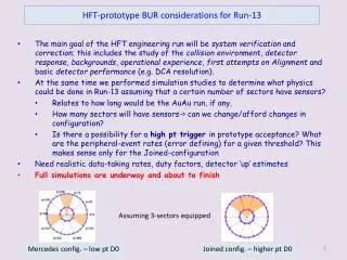
East Pole Tip installation H. Wieman
FINISH START START Current status and future plans Hardware: • Mother board • Daughter card • Stratix card • DDL • 3 MimoStar2 telescope 55Fe calibrations Analysis and evaluation Gain adjustment Firmware: • Testing interface • JTAG • Full frame RDO (CDS) • DDL – RORC • Cluster finder, cluster FIFO • Full functionality interface ALS (1.2 GeV electrons) Tests, evaluation, tuning Software: • lab tests – 55Fe calibrations • Complete system control BNL Tests outside and inside the magnet • Infrastructure • DONE & WORKING DONE & WORKING
Telescope Calibration Results • Fe55 calibrations after assembling the telescope head
Noise @ ALS (no markers) ENC 33.9 e- ENC 37.5 e- ENC 34.6 e- ENC 39.1 e- ENC 33.5 e- ENC 37.9 e-
Full-frame readout (complete array 12b/pixel) STD diode expected MPV 46 ADC measured MPV 49 ADC C1 > 25 ADC C2 > 14 ADC C1 > 40 ADC C2 > 14 ADC C1 > 30 ADC C2 > 14 ADC C1 > 25 ADC C2 > 0 ADC C1 > 10 ADC C2 > 0 ADC C1 > 20 ADC C2 > 14 ADC
Full-frame readout (complete array 12b/pixel) RADTOL diode expected MPV 40 ADC measured MPV 43 ADC C1 > 25 ADC C2 > 14 ADC C1 > 40 ADC C2 > 14 ADC C1 > 30 ADC C2 > 14 ADC C1 > 25 ADC C2 > 0 ADC C1 > 10 ADC C2 > 0 ADC C1 > 20 ADC C2 > 14 ADC
Telescope @ BNL • Tests outside of magnet • Noise at the same level as in ALS
Conclusions • Next step: install telescope head in the STAR magnet • We’re all set and waiting for the data taken in the STAR environment • The end
Backup slides • Event data format • Data rate reduction in the system
Firmware – overview Another schematic will go here scalable
Proposed event data format per data stream from MimoStar output Fixed Length Header (64 bytes) Byte 1-4 AAAAAAAA tag for beginning of event 5-6 3-bit control shell command, 5 bit argument 7-8 Trig command bit0-3, DAQ command bit 0-3 (from TCD) 9-10 12 bit Token (from TCD) 11-12 snapshot of FE/NIOS commands and status bits. 13-14 Mimostar position on ladder, ladder address 15-64 reserved (for future use, possible comment space?) All set to 0 unless specified The termination word is the one used for the RORC/SIU and consists of EEEEEEEE. In the data taking in STAR, we will deliver events on a ladder/MB basis where the data has the form (per ladder)
Data Rates (As in 2006) • 100 hits/cm2 Inner Layer, 20 hits/cm2 Outer Layer (L = 1027) • Average event size = 90 KB • Event size = 90 MB/sec at 1KHz • 24 fibers • 12 RORC (4 readout PCs)
SOFTWARE Lab tests: • Readout mode (raw/cds data, event based readout) • Raw data analysis (offline noise calculation and cluster finding for calibrations with Fe55 Full system: • Remote control (readout mode, status monitoring) • Noise calculations for finding a hot pixel map • Online monitoring (hits display, simple track association) • Integration with STAR DAQ • DONE & WORKING • Under development
Lab verification • Fe55 calibrations IPHC – results from Strasbourg Mezz. Full – chip bonded on a mezzanine card Mezz. Part – chip bonded on a mezzanine card with part of the bonds (like for a flex cable) Flex1 – only on flex cable in the hft system Flex2 – two chips in parallel in the hft system • The noise doesn’t come from the DAQ system (~1 ADC)