Download
1 / 74
780 likes | 1.08k Vues
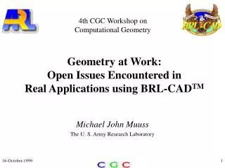
4th CGC Workshop on Computational Geometry. Geometry at Work: Open Issues Encountered in Real Applications using BRL-CAD TM. Michael John Muuss The U. S. Army Research Laboratory. Why We Model. Storytellers communicate feelings to people. “Skin-deep” models are fine for movies.

E N D
4th CGC Workshop on Computational Geometry Geometry at Work:Open Issues Encountered inReal Applications using BRL-CADTM Michael John Muuss The U. S. Army Research Laboratory
Why We Model • Storytellers communicate feelings to people. • “Skin-deep” models are fine for movies. • We are predicting or matching physical phenomena: • Energy levels received by a sensor. • Damage statistics of live-fire tests.
Integrated Survivability/Lethality Analysis Products Modeling is OnlyOne Part of the Process Model Analyze Experiment Today’s topic is modeling and simulation.
Modeling Means Different Things... • Goal: Re-creating the real-world in simulation: • Re-creating individual laboratory tests. • Science & Engineering community starts here. • Re-creating real proving grounds. • Re-creating training centers and actual exercises. • Re-creating combat locations and scenarios. • Training community & wargamers start here.
Meeting the Simulation Challenge • Engineering-level geometric detail. • Physics-based simulation. • Realistic 3-D atmosphere, ground, and sea models. • Fast: Hardware-in-the-loop, man-in-the-loop. • Real-time, near-real-time, Web, and offline. • Common geometry. • Common software. • Massively parallel processing.
Image Generation “If you can’t see it, you can’t shoot it.” Vulnerability/Lethality Analysis “Will the bullet bounce off?” Two Types of Simulation
OUTLINE • I. BRL-CADTM and Targets • II. Shooting Bullets • III. Making Pictures
BRL-CADTM Primitive Solids sphere spheroid ellipsoid right circular cylinder right elliptical cylinder truncated right circular cone truncated elliptical cone intersection of halfspaces edge-contracted topo. cubic 6-hedron truncated general cone topo. cubic 6-hedron right triangular prism quadrilateral pyramid tetrahedron elliptical-ring torus right parabolic cylinder right hyperbolic cylinder elliptical paraboloid elliptical hyperboloid torus waterline-based polyhedron halfspace voxel data general polyhedron trimmed NURBS revolved plane curve extruded plane curve Path and bend convex hull of two spheres extruded bit map
CSG Boolean Operations wedge (wedgeÇ block) -cylinder cylinder block wedgeblock-cylinder block- (wedge cylinder)
Hierarchical Database Organization tank crew hull turret suspension turret_armor turret_interior gun bore_evacuator gun_tube breech Directed Acyclic Graph cylinder_1.s cylinder_2.s cylinder_3.s
One Geometry,Multiple Uses • To compute ballistic penetration & vulnerability: • Need 3-D solid geometry and material information. • The same targets are also useful for: • Signatures: Radar, MMW, IR, X-ray, etc. • Smoke & Obscurants simulation. • Chem./Bio agent infiltration. • Electro-Magnetic Interference. • BRL-CADTM is the basis for all our simulations.
Ray Tracing Starting point distance, obliquity, normal, curvature, etc.
Evaluating Boolean Expressions in CSG C A B Segments: ABC: 100 010 011 010 110 A B – C
Vulnerability/LethalityAnalysis Process Initial threat/target conditions Level 1 Component damage Level 2 physics, penetration models, ... System capability engineering, criticality analysis, ... Level 3 System utility operations research, missions, scenarios, ... Level 4
Computing Component Damage(Level 1 to Level 2 Mapping) CSG model of vehicle Specification of Spall munition performance Ray tracer Shotlines representing Vulnerability model Penetrator+spall paths Damage Results
Ray-tracing Through a Target rear armor fan transmission sump starter engine fire wall HE round armor-piercing rounds glacis armor
Penetration Results Perforation into internal volume Residual penetration inside internal volume 0 900 mm
Experimental Data: Perpendicular jet. Simulation Results: Oblique impact. Spall: a Secondary Damage Mechanism Thousands of fragments to track! Each generates another ray. Behind-Armor-Debris is BAD.
Mapping from Damageto Capability (L2->L3) Fault Trees map component failure to subsystem capability. Main Armament Fault Tree Main Armament Subsystem Subsystems per vehicle: 50-100
Is a Ray aGood Approximationfor a Fragment? • Sensor pixel. 0.01mm diameter-- OK. • Rifle bullet. 5.56mm diameter -- Maybe. • Tank bullet. • 30-120mm diameter -- No.
In General: No! • Real particles have non-zero cross-section. • A 0-thickness ray is not the best approximation. • A real fragment will hit wires that the ray will miss. • Most damage is done by spall cloud. • Has a large total surface area. • We sample density distribution with 1000’s of rays. • This greatly under-samples the target geometry.
Beam or Cone Tracing? • Obvious solution: • Model particle path as a cylindrical beam. • Model light ray as a cone. • Solve cylinder-vs-object or cone-vs-object intersections. • Such intersections yield complex volumes.
A Ray Slipping ThroughComplex Geometry Object on Centerline Ray
A Beam throughComplex Geometry Object on Centerline r > 0
Objects in the Beam Object on Centerline
A Simplified Viewof the Relationships Object on Centerline But it isn’t this simple!
Relations Along a Ray entirely-precedes occults appears-before
Difficulties withCone-tracing • Intersection with more general solids is expensive. • E.g. height field, or t-NURBS. • Representation of the results is difficult. • No exact representation of the volume. • At best, result could be some kind of B-rep. • No convenient abstraction of volumetric result. • Partially ordered sets! • Utilizing the results is difficult. • How to compute ricochet -vs- penetration?
A Plea! • Are there any good representations for these intersection volumes? • Are there any good abstractions for these intersection volumes?
Our Short-Term Strategy • Fire additional rays distributed around main ray. • Tightly coupled with space partitioning, for high performance. • User-selected patterns. • Peripheral rays intersected only when main ray does not intersect geometry. • Heuristics for choosing a single interval as “most representative” of material in that region. • Reduces missing small objects in beam path.
What is PST? • PST = PTN and SWISS, Together! • PTN = Paint-the-Night • Real-time polygon rendering • From CECOM/NVESD • SWISS = Synthetic Wide-band Imaging Spectra-photometer and Environmental Simulation • Ray-traced BRL-CAD™ CSG geometry • From ARL/SLAD
Application of PST • The image generator is just one component of a larger simulation. E.g. MFS3, or missile simulation. Full Platform Simulation or HWIL Full Platform Simulation or HWIL Full Environment Simulation PST 6 DoF Flight Dynamics ATR Images Motion_t Control Decisions
Paint-the-Night • 8-12 micron IR image generator. • SGI Performer based. • Uses outboard image processor for sensor effects. • A large highly tuned monolithic application • With exceptionally high performance. • Highest polygon rates seen on a real application. • Individually drawn trees (2 perpendicular polygons) • Individually drawn boulders.
SWISS • A physics-based synthetic wide-band imaging spectrophotometer • A camera-like sensor • Looks at any frequency of energy. • A set of physics-based virtual worlds for it to look at: • Atmosphere, clouds, smoke, targets, trees, vegetation, high-resolution terrain. • A dynamic world; everything moves & changes.
A Grand-ChallengeComputing Problem • Real targets, enormous scene complexity, > 10Km2. • Physics-based hyper-spectral image generation. • Nano-atmospherics, smoke, and obscurants. • Ray-traced image generation, exact CSG geometry. • Near-real-time (6fps). • Fully scalable algorithms. • Network distributed MIMD parallel HPC. • Image delivery to desktop via ATM networks.
Advantages of a Ray-Tracing SIG • Allows reflection, refraction: • Windshields, glints. • Branch reflections, 3-5 µm. • Atmospheric attenuation, scattering. • Individual path integrals. • Accurate shadows: • Haze, clouds, smoke. • Multiple light sources: • Sunlight, flare, spotlight. 2nd-Generation FLIR image, 8-12 µm (Downsampled to 1/4 NTSC)
CSG Rendering Advantages • Ray-traced CSG is free from limitations of hardware polygon rendering: • No approximate polygonal geometry. • No seams, exact curvatures. • Exact profile edges. Important for ATR! • No level-of-detail switching, no “popping”. • Full temperature range in Kelvins, not 0-255. • Unlimited spectral resolution, not just 3 channels.
Cruise Missile Shadow Ridge Profile Missile Shadow Terrain Quantization
Target Geometry Complexity • Need at least 1cm resolvable features on targets.
Complex Geometry Today • < 1cm target features. • 1m terrain fence-post spacing • Three-dimensional trees: • Leaves. • Bark. • Procedural grass, other ground-cover. • Boulders, other clutter. Current Developmental