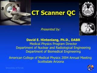
CT Scanner
CT Scanner. Presented by: Dr M A Oghabian Medical Physics Department, Tehran University of Medical Sciences. Computed Tomography. CT uses a rotating x-ray tube, with the beam in the form of a thin slice (about 1 - 10 mm)

CT Scanner
E N D
Presentation Transcript
CT Scanner Presented by: Dr M A Oghabian Medical Physics Department, Tehran University of Medical Sciences
Computed Tomography • CT uses a rotating x-ray tube, with the beam in the form of a thin slice (about 1 - 10 mm) • The “image” is a simple array of x-ray intensity (Projections), and many hundreds of these are used to make the CT image, which is a “slice” through the patient
Third generation CT Scanners(Rotate/Rotate , Wide fan beam) • Wide fan beam • More than 800 detectors • No translational motion • Scan time ~ 0.5 Sec.
A look inside a rotate/rotate CT Detector Array and Collimator X-Ray Tube
4th Generation CT ScannersRotate/Stationary • Fan beam geometry • More than 4800 detectors
5th generation: Electron Beam CT (EBCT) - x-ray source is not x-ray tube but a focused, steered, microwave-accelerated EB incident on a tungsten target. - It has no moving parts . - Target covers one-half of the imaging circle; detector array covers the other half. • Images in • less than • 50ms.
EBCT(CONT’D) • There are 4 targets and 4 detector arrays resulting in 4 contiguous images simultaneously. • Each solid -state detector consists of a luminescent crystal and cadmium tungstate • coupled with silicon photodiodes. • Heat dissipation is no problem in EBCT. • Developed for fast imaging. • Used for cardiac imaging
A Look Inside a Slip Ring CT Note: how most of the electronics is placed on the rotating gantry X-Ray Tube Detector Array Slip Ring
Reciprocating rotation (A) versus fast continuous rotation using slip-ring technology (B)
Comparison of data acquisition for axial and helical technologies.
Comparison of the accuracy of 3D reconstruction for conventional (A) and spiral/helical (B) CT scanning.
MULTISLICE SPIRAL CT • Introduced at the 1998. • They are based multiple detector. rows ranging between 8, 16, 24, 32 and 64 depending on the manufacturer. • The overall goal is to improve the volume coverage speed performance. • Complete x-ray tube/detector array rotation in less than 1s. • Partial scan images can be obtained in approximately 100ms.
Multislice CT, where up to 64 variable thickness slices can be collected simultaneously • CT fluoroscopy, where the patient is stationary, but the tube continues to rotate • 3-dimensional CT and CT endoscopy
Detector Configurations X-ray Tube Focal Spot X-ray Beam Collimator a • 4 x 1.25 mm Detector Configuration 16-row Mosaic Detector Flex Connector A Flex Connector B Diode FET Switching Array
Detector Configurations X-ray Tube Focal Spot X-ray Beam Collimator 4 x 2.5 mm Detector Configuration 16-row Mosaic Detector Flex Connector A Flex Connector B Diode FET Switching Array
Detector Configurations X-ray Tube Focal Spot X-ray Beam Collimator 4 x 3.75 mm Detector Configuration 16-row Mosaic Detector Flex Connector A Flex Connector B Diode FET Switching Array
Detector Configurations X-ray Tube Focal Spot X-ray Beam Collimator 4 x 5.0 mm Detector Configuration 16-row Mosaic Detector Flex Connector A Flex Connector B Diode FET Switching Array
Multi slice CT collimation 5mm 2,5mm 1mm 0,5mm
Speed: Single vs. 4 Slice Single Slice 235 mm 5 mm 31 240 255 mm 5 mm 34 300 65 17,720 4 slice Chest Coverage Thickness Time (s) mA Abdomen/Pelvis Coverage Thickness Time (s) mA Scan Time (s) Tube Load (mAs) 235 mm 5 mm 8 240 255 mm 5 mm 9 300 17 4,725
MULTISLICE IMAGING(CONT’D) ADVANTAGES • Improved spatial resolution this advantage improved MPR,3D images. • Reduction of radiation exposure. • Motion artifacts are greatly reduced. • Patient breathhold is much less demanding. • Imaging larger z-axis volume in less time is possible with MI. • Less contrast medium required. • Because of imaging speed, coronary artery is comparable with EBCT. • Improved accuracy in needle placement CT fluoroscopy.
Clinical Benefits Of Multi-Slice Multi-phase Organ Studies • Liver – Pancreas Arterial, Renal Nephrogram Arterial Phase Scanning • Hypervascular Tumors CT Angiography • Multi-Plane Reconstructions, Contrast Enhancement New CT Applications • CT fluoroscopy • CT Colonography • Cardiac: morphology, function • Advanced Lung Analysis
CT Fluoroscopy • Real Time Guidance • Great Image Quality • Low Risk • Faster Procedures
REAL-TIME CT FLUOLOROSCOPY • CT fluoroscopy acquire dynamic images in real time. • Fast continuous imaging, fast image reconstruction & continuous image display. • Patient movement is low during Tube rotation. • Fast image Reconstruction algorithm is required.
CT ANGIOGRAPHY (CTA) • CTA allows maximum visualization of the pulmonary artery and its segmental braches. • CTA requires low kVp and MA, for example 90Kvp/100mA. • CTA employs MIP and MPR to maximum advantage.
CT VIRTUAL REALITY IAMAGING • The use of virtual reality is the creation the inner views of tubular structures. • Offers both endoluminal and extra luminal information. • It reduces complication (eg. infection and perforation). • Four requirements: • data acquisition • image processing • 3D rendering • image display and analysis.
CT Scanner • Generator • High frequency, 30 - 70 kW • X-ray tube • Rotating anode, high thermal capacity: 3-7 MHU • Dual focal spot sizes: about 0.8 and 1.4 • Gantry • Aperture: > 70 cm of diameter • Detectors: gas or solid state; > 600 detectors • Scanning time: <1 s, 1 - 4 s • Slice thickness: 0.5 - 10 mm • Spiral scanning: up to 1400 mm
Gas detector (xenon) • Fast detection response • High Sensitivity • Stability against Radiation damage • Stability against Temperature & Humidity • Higher Dynamic range • But less Quantum efficiency • Inherent collimation • Total DQE(Detective Quantum Efficiency) • = 60 percent
Solid detectors (Ultra Fast Ceramics) UF • Godalinium OxiSulphade has uniform sensitivity and fast response time • Need collimation so: • Less Geometric Detection Efficiency (GDE) • Total DQE(Detective Quantum Efficiency) • = 80 percent
MTF of CT detectors • MTF depends on: • Geometric characteristics and size of detector • Time response of the detectors • Cross Talk from adjacent projections or Slices due to long Decay time • Decay time is about 3 s • Afterglow is about 10-4 after 3mS • Design type and construction of detector arrays, (detector separation and distance)
number=1000×(mpixel-mwater)/mwaterDetector Calibration CT CT Projections and Reconstruction
CT scanner Image processing: • Reconstruction time: • 0.5 - 5 s/slice • Reconstruction matrix: 256x256 – 1024x1024 • Reconstruction algorithms: • Bone, Standard, High resolution, etc • Special image processing software: • 3D reconstruction • Angio CT with MIP • Virtual endoscopy • CT fluoroscopy