Download
1 / 37
370 likes | 496 Vues
Dynamical Polarization of neutron beams. G. Badurek, C. Hartl, E. Jericha Atominstitut, Vienna University of Technology. Dynamical Polarization of Neutron Beams. Idea & Motivation. Conventional neutron polarizers Waste >50% of incident beam intensity.

E N D
Dynamical Polarizationof neutron beams G. Badurek, C. Hartl, E. Jericha Atominstitut, Vienna University of Technology
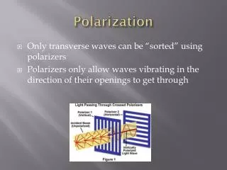
Dynamical Polarization of Neutron Beams Idea & Motivation • Conventionalneutron polarizers Waste >50% of incident beam intensity. • Gedankenexperiment:What, if we turn the unwanted spin component into the „right“ direction?use 100% of intensity
Dynamical Polarization of Neutron Beams Concept • No interaction with matter • Flip„wrong“ spins • Accept atiny energy shift(~10-5) • In principleloss-free:100% transmission100% polarization First Proposal: Badurek, Rauch, Zeilinger Z. Phys. B 38 (1980) 303
Dynamical Polarization of Neutron Beams Energy Change Spin-dependent engergy shift: • Spin flipeffectspotential energy only • 2 xkinetic energychange (same direction)at themagnet borders
z x -y Spin Precession Region Transition regionbefore and behind the spin precession region causes anadiabatic spin rotationinto and from the x-direction. Two /2-turnersat entrance and exit of the precession region: • 1st spin turnerstartsspin rotation (turns spin into (z-y)-plane) • 2nd spin turnerstopsspin rotation (turns spin back into x-direction)
Polychromatic Pulsed Beam Polarization • Polarizepolychromaticneutron beams • Pulsedsource required • TOFpathbefore polarizer mapswavelength time • Monoenergeticpolarization conditionfor each wavelength time-dependent operation
Monte-Carlo Simulation: Concept • 3-dim.classical spin rotation • Simple field geometry • Continuousmonochromatic(static) or pulsedpolychromatic(time dependent) setup • Process „neutron events“ (t, x, v, P) step by step • Calculation exact where possible • RF flipper,, DC flipperand2nd/2 turner:„Krüger arrangement“
z y x D t0 t1 = t0+D·v Neutron Spin Motion inside a “Krüger-arrangement“ parameters: RF field frequency Effective Larmor frequency vector:
z y x D t0 t1 = t0+D·v Neutron Spin Motion inside a “Krüger-arrangement“ Equation of motion: S S‘(t) : P(t)=G(t)·P’(t) In the primed system the rotation axis lies statically in the x’-axis! Solution:
1 0.5 0 -0.5 -1 1 0.5 0 -0.5 -1 -1 -0.5 0 0.5 1 1 Neutron Spin Motion inside a “Krüger-arrangement“ Movement of the polarization vector‘s tip Example parameters (resonance case):
Dynamical Polarization of Neutron Beams Typical Result of Monte-Carlo Simulation Source Pulse Duration Incident flight path: 60 m Splitting Field: 4 10 T Precession Length: 1 m
Tensorial Neutron Tomography of magnetic samples G. Badurek, E. Jericha, H. Leeb, R. Szeywerth Atominstitut, Vienna University of Technology
Tensorial Neutron Tomography Idea & Motivation • Determination of magnetic structures in bulk ferromagnetic materials Unique reconstruction by tomographic methods. • Path-ordering effects in neutron spin rotationDevelopment of novel reconstruction alogrithms.
Tensorial Neutron Tomography Concept Perfect crystal neutron interferometer Set-up for neutron interferometric spinor tomography. • Combination of neutron depolarization concepts and neutron interferometry.
Spin rotation operator Quality of the reconstruction
Reconstruction quality – traditional methods 1 G. Badurek et al., Physica B 335 (2003) 114
Reconstruction quality – traditional methods 2 reasonable reconstruction up to 2 µm pixel sizes
Summary of novel reconstruction algorithms • Elimination procedure • Separation procedure • (Sums of separated logarithms) • Modified algebraic reconstruction technique • ART with path ordering • ART with converging projections • Taylor series expansion
Elimination procedureneutrons with multiple velocities • Elimination of path ordering effects using experimental data of multiple different velocities reconstruction via traditional ART or FBP
Reconstruction quality – multiple wavelengths good results up to pixel sizes of 5-6 µm
Multiple wavelengths – influence of noise pixel size 3 µm problem: uncertainties in each term and large g-factors for neighbouring velocities
Separation procedureseparation of line integrals andpath ordering effects L ... contains line integral without path ordering K ... contains all path ordering effects U ... determined by experiment solved by iteration L(0) taken from a model describing the sample quality of the reconstruction essentially determined by the applicability of the model
Separation procedure - iteration by inverse Radon transformation traditional methods (ART or FBP) taking full path ordering into account the measurement enters here good results up to pixel sizes of ~ 4 µm
Reconstruction quality – separation procedure a) individual projections from the angular range 0 – 2p b) averaged quantities from the projections q & q+p
Modified ARTtaking path ordering into account • ART performs the inverse Radon transformation by solving a system of linear equations for discretized pixel structures • Path-ordered integrals also have to be written as linear equations to apply ART → linear approximation (with B(i) being the reconstruction for the current iteration):
Iteration procedure for the modified ART • Solving this system of linear equations changes the standard ART algorithm just in one way: pseudo-projections are no longer line integrals but path-ordered integrals. • The algorithm looks like this: • Result: full convergence for 4-5 µm for a 20x20 pixel structure, slightly better than prior methods with possible advantages concerning limited angle data
Modified ART 2assure convergence of the projections aim - convergence correction for a specific pixel proportional to the neutron path length across this pixel iteration procedure initial condition
Modified ART – method 2 in case of convergence no convergence skip this projection for reconstruction • full convergence up to 5 µm for a 20x20 pixel structure • advantages for incomplete data sets • relatively robust against uncertainties from counting statistics and pixel deformations
Modified ART 3linearization by Taylor series expansion magnetic field distribution n-th iteration series expansion coefficients iteration procedure
Reconstruction quality – modified ART a) results for the modified ART b) results for modified ART method 2 c) results for modified ART method 3 10 iterations for each method only