Download
1 / 33
340 likes | 456 Vues
Learn about block diagrams in audio technology for theater productions and sound systems. Discover how to create and interpret block diagrams, avoiding costly mistakes in system installation. Explore symbolic conventions and analysis techniques. Enhance your skills in preparing sound systems for performances and consultations.

E N D
THTR 357-Intro to Audio Technology Tech Lecture 7: Block Diagrams
Introduction • This section discusses block diagrams and speaker plots, with specific application to theatre productions. • Remember that although there is still a great deal of variety used in graphically notating sound systems (even thought sub-committees exist in AES USITT and NSCA to standardize these symbols)
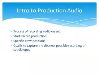
7.1 General Discussion • A block diagram is a graphic description of the signal path through a device, or series of devices. • The block diagram consists of individual functional entities connected in a specific way. • The purpose of a block diagram is to present the logical structure of equipment in simple, readily accessible form.
7.1 General Discussion • Example:The sound designer, or system engineer sends a block diagram to the shop, and the shop builds and installs the system according to the block diagram. • This happens frequently on touring shows, or shows designed by out of town designers, etc. • The system engineer or designer may never see the system until after it has been fully installed. Mistakes can be extremely costly, both in terms of time and money. • Because of the high cost of mistakes, great care must be exercised when preparing block diagrams.
7.1 General Discussion • Examples of Block Diagrams: • Signal processing equipment (mixers, delays, eq., etc, found in product data sheet • Instruction manual • System Block Diagram (e.g. theatre productions, touring shows, etc. NOTE: see Section 17, pp. 213-224 of Yamaha Manual) • Be carefull not to confuse block diagrams with schematic (component level) diagrams.
7.1 General Discussion • Two Fundatmental Caveats: Always organize the block diagram to show how the signal flows through the system. Remember that the block diagram presents the logical organization of a device or a system.
7.1 General Discussion • We will concentrate on symbols commonly used in System Block Diagrams, such as those used to prepare sound systems for the Performing Arts, sound system consulting and contracting, etc. • For variations that relate to reading or creating component block diagrams, consult the text.
7.2 Symbolic Conventions7.2.1 Amplifiers Preamp or Single Channel Power Amplifier Two Channel Power Amplifier • Amplifiers are always denoted by a triangle. • System Block Diagrams typically show power amplifiers (although outboard preamplifiers appear as triangles also). • We use two types: single channel (often used with amps bridged for mono output), and dual (most common type, used with amps powering two full range loudspeakers, or the low frequency and high frequency drivers in bi-amped systems).
7.2 Symbolic Conventions7.2.2 Other Devices Unity Gain or Attenuating Device • All other devices that exhibit unity gain, or loss are denoted with a rectangle, except loudspeakers. • The name of the device is centered in the box, or placed nearby if it is not practical to include it in the box. • All devices on the block diagram (including amplifiers and loudspeakers) must show make and model number.
7.2 Symbolic Conventions7.2.2 Other Devices • Straight lines of medium thickness are used to show equipment interconnection. • Where there is potential ambiguity regarding inputs and outputs, the name of the input or output (as it appears on the rear of the device) is shown in the box. This is almost always the case with mixing consoles.
7.2 Symbolic Conventions7.2.3 Loudspeakers Biamplifierd Loudspeaker Loudspeaker • Loudspeakers are shown as a single driver, even if they employ passive crossovers • Biamplified loudspeakers are shown as separate elements to make connection to amplifier channels clear.
7.2 Symbolic Conventions7.2.4 Other Commonly Used Symbols • A Title Block should include the following information:
7.3 Notational Conventions • Block diagrams usually are created so that signal flows from left to right--inputs on the left, and outputs on the right. • Feedback loops such as signal processors will typically be routed in the opposite direction.
7.2 Symbolic Conventions7.3 Notational Conventions • It is usually not necessary to provide individual labels for separate channels of two channel devices such as processors, amps and speakers. Convention dictates that the top or left component is the left channel or channel 1, and the bottom or right component is the right channel or channel 2.
7.5 Analysis of Simple Block Diagrams • Pin 1 of XLR is ground • Pin 2 (hot) is transformer isolated • Differential input amplifier (e.g. balanced) vs. single-ended • Rotary gain controls gain of amplifier, not level going into amplifier 6-40 dB
7.5 Analysis of Simple Block Diagrams • Pin 2 (hot) goes to + of amp (e.g. normal polarity) • Pin 3 (neutral) follows - sign through to pin 3 of line output • Note that most single ended amplifiers invert the polarity of the signal. This may or may not be restored to normal polarity internally
7.5 Analysis of Simple Block Diagrams • 11 stages of EQ in series: High Pass Filter (variable frequency) Low pass filter (variable frequency) 9 Bands of graphic EQ with variable boost/cut • Transformer isolated balanced output
7.5 Analysis of Simple Block Diagrams • Non-inverting circuit in which pin 2 is hot. ALWAYS make sure by consulting owners manual or checking. • Fixed gain • EQ/Bypass switch • EQ feeds single ended non-inverting amplifier
7.5 Analysis of Simple Block Diagrams • Block diagram shows only logic structure of device. • Input control level in a buffering amplifier • Low pass anti-aliasing filter to prevent digital distortion. Dry signal picked off after this point.
7.5 Analysis of Simple Block Diagrams • Feedback combined with original signal next. Note that feedback loop is analogue. Note polarity reversal switch and level control in feedback loop. Feedback allows creation of multiple echoes, reverberation, flanging, etc. depending on time delays chosen.
7.5 Analysis of Simple Block Diagrams • A/D converts analogue to digital. • Memory delays signal (note user controls). • D/A follows and converts signal back to analogue. • Dry/wet mix control followed by low pass filter to remove memory's clock frequency.
7.5 Analysis of Simple Block Diagrams • Voltage controlled oscillator (VCO) controls clock rate which controls delay time. Low frequency oscillator (LFO-typically .01-20 or 100 Hz) allows delay time to be modulated by, in this case, a triangle wave. LFO frequency controls rate of modulation.
7.6 The Speaker Plot • The Speaker Plot is a separate but crucial diagram used in sound system design. • The Speaker Plot is not intended to show how equipment is connected, or to give an understanding of signal flow, but to depict the location of sound system components that have an important physical relationship to the theatre space.
7.6 The Speaker Plot • The speaker plot includes all loudspeakers, practicals (i.e. sound effects devices such as doorbells, wind machines, telephones, etc.), racks, consoles, microphones and cables shown in their exact location in the space. • Where possible, and necessary to the proper installation, objects are shown scaled to proper size.
7.6 The Speaker Plot • Where possible, and necessary to the proper installation, objects are shown scaled to proper size. In situations where an object is physically smaller than can be accurately depicted, or size is not of concern in the implementation, a symbol may be used, accompanied by an explanatory key. • If the Sound System Designer is responsible for intercommunications systems, these locations must also be included on the Speaker Plot.
7.6 The Speaker Plot • The Speaker Plot is typically constructed using the Ground Plan and Section of the set and auditorium, as furnished by the scene designer. • Hopefully, the Ground Plan and Section will be submitted in software form, to make it easy for the Sound System Designer to modify into a useful form.
7.6 The Speaker Plot • These modifications include: 1. Remove all non-essential details from the plot such as set dimensions, labels, construction notes, etc. If an item has no bearing on the sound installation it probably is not needed on the plot; 2. Keep the basic outline of the set, or sets, but use a very light guage pen thickness to ensure that the scenic elements always appear in the background; 3. Use a slightly thicker pen to draft cables, including snake, speaker cables, etc. 4. Use an even thicker guage to draft objects such as speakers, console location, rack locations, etc.
7.6 The Speaker Plot • 5. Make sure that speaker dimensions are accurate, and shown on both the Ground Plan and the Section. This is necessary to make sure that: They fit in the scenery the way they are intended to fit; They aren't in the way of other scenery; They have clear, unobstructed sightlines to the audience, if desired; The location of the horns is clearly specified. 6. The Speaker Plot is typically given to the Tech Director, who is responsible for any working drawings that need to be accomplished to get the speakers rigged, located in scenery, etc.
7.7 The Shop Order • The final component of the technical drawings is the shop order. • The shop order is used to collate every piece of equipment required by the production. • Rental Shops typically prepare their bids based on the shop order, and producers base their budgets on the shop order. • Therefore, every single piece of equipment, cable, interconnect, direct box, transformer, snake, etc., must be accurately specified in the shop order.
7.7 The Shop Order • If this doesn’t happen, there will typically be no money in the budget to rent additional equipment, and the sound designer will have to figure out how to do without. • Shop orders that are consistently erroneous or incomplete will cause sound designers or systems engineers to get very good at job hunting!