RFID Human Motion Alarm System
RFID Human Motion Alarm System. Chris Hirsch & David Huskey. Automated identification method Lightweight, portable Tags can be read from several meters away, (sometimes) beyond line of site of reader Passive RFID tags have no internal power supply

RFID Human Motion Alarm System
E N D
Presentation Transcript
RFID Human Motion Alarm System Chris Hirsch & David Huskey
Automated identification method Lightweight, portable Tags can be read from several meters away, (sometimes) beyond line of site of reader Passive RFID tags have no internal power supply Small electrical current induced in the antenna by the incoming RF signal provides just enough power for the tag to power up and transmit a response back. Introductionto RFID
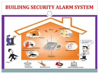
Objectives • Incorporate RFID into room alarm systems • Sound an alarm when an unaccompanied unauthorized intruder is in the protected room • Transmit data via serial to a computer where it can be monitored by security • Design an alarm system that is user friendly • Design an alarm system that is robust enough to detect any intruder using any method of entry
Inputs: RFID Reader IR Motion Sensor 16 Button Keypad Outputs: Siren LEDs RS-232 Port RFID Transponder Antenna Siren / LEDs Controller RFID Reader PC Output IR Motion Sensor Keypad Input Basic Abstract Design
Runs program that monitors voltages from the inputs of the system (keypad, motion sensor, and RFID reader) in an infinite loop. Controls all outputs of the system (Siren, LEDs, and PC display) by setting voltages on output pins. PIC16F877A Microcontroller
1. Keypad State 3. Siren State Keypad Deactivated RFID Deactivated Correct Keycode Tag Not Present Siren Deactivated Motion Detected 2. RFID State Correct Keycode Tag Present Keypad Activated Keypad Activated Siren Activated (when Keypad & RFID activated) Microcontroller Flow Chart
SkyeTek M9 RFID Reader • Chosen over the Texas Instrument RFID Reader for its superior range • Receives commands from and transmits responses to the controller through an RS-232 port at 34.8 kbps • Operates at a frequency of 915 MHz and output power of 500 mW
Grayhill Keypad • 16 buttons – 16 possible interconnections • 4x4 matrix that can be probed at the 8 output pins • Extra buttons allow for adding additional features in the future
Microcontroller: Keypad Input • Sets pins 1-4 to high sequentially and observes pins 5-8 for connections to determine if a key has been pressed. • Correct sequential Key-Code from the user activates / deactivates the alarm system
6000 PIR Infrared Motion Detector • Chosen for its long range and low cost • Requires +12 and –12 volts for power • Outputs a signal of 1.1 volt when motion is detected
The controller monitors the voltage on the motion detector output. Microcontroller uses the ADC function to monitor the AC voltage. Converts a continuous signal to a discreet digital number from 0 to 1024 (2^10) When voltage rises above 50mV or 10 on the ADC scale on this input (and the alarm is in active mode) the alarm is triggered. Microcontroller: Motion Detector Input
Output Components • Sonalert Siren • Draws little current at 5 volts (~2 mA) • Controlled by the Microcontroller • LEDs • Red and green LEDs have a voltage drop of 2.1 volts and are connected to 560 ohm resistors in order to limit the current sourced by the PIC to approximately 5 mA • RS-232 Port PC Output • Connected to the microcontroller via the MAX-232 chip • 38.4 kbps and only requires a wire for transmitting to the computer and a wire for ground
Red LED can be turned on and off by entering correct key-code. Green LED is on when the controller considers no tags to be in the room. When both LEDs are on, unauthorized personnel are to stay out of the room, because the alarm is in active mode. Microcontroller: LED Output
Beeps (voltage high for 150 milliseconds) once when a tag is seen entering the room and twice when a tag is seen exiting. Longer Beeping for a 10 second grace period when the PIC decides that there is an intruder. Continuous noise from the siren if the alarm is not deactivated after the grace period. Microcontroller: Siren Output
Information is sent to the computer as ASCII characters through an RS-232 port connected to the PIC microcontroller through the Max-232 chip. Microsoft HyperTerminal displays the text. Shows when the alarm is activated and deactivated. Shows which ID tags enter and exit the protected room. Microcontroller: Computer Output
Main PCB Components & Enclosure • PIC Microcontroller • The brain of the alarm system • FOX 20MHz Oscillator • Clock input for the PIC • 5V Voltage Regulator • Steps voltage down from 12 volts to 5 volts • Max-232 Chip & 0.1 microfarad Capacitors • Converts TTL voltages to RS-232 voltages and vice-versa.
TESTING & VERIFICATION RFID READER &MOTION DETECTOR
Counter Code Implemented • Each user could only exit and enter after ten iterations of the coded loop • User held tag parallel to reader at various distances
Null Code Implemented • Each user could only exit and enter after the PIC had received a null response from the reader • User held tag parallel to reader at various distances
Both Codes Implemented • User can only exit and enter after null code is received and after 3 iterations of the loop had passed • User held tag parallel to reader at various distances
Multiple User Test • Test to make sure the system could handle multiple users at once • Tested in single file and side by side • User held tag parallel to reader at various distances
Wallet & Denim Test • Through a wallet at under a foot • Through a denim pocket at under an inch • Due to the low power output of the reader as well as the orientation of the tag
Never Never 40˚ 40˚ 50% Detection Rate 50% Detection Rate 50˚ 50˚ Always Always Testing the Motion Detector
Project is a success Alarm sounds when the system is in active mode and an unauthorized intruder is in the 40’ x 40’ room. Information about current ID tags in the room and the state of the alarm system can be transmitted serially to a PC for observation. The design is user friendly. Users are able to quickly identify the beeps and LEDs to know if their ID tag has been scanned. Successes
RFID Challenges Certain materials greatly reduce range of RFID tag detection rate In Wallet Range – <1ft for reliable detection rate In Denim Pocket range - <1in for reliable detection rate Standing just out of range of the RFID antenna (>4ft) can sometimes cause erroneous, unwanted tag scans Challenges
More RFID Challenges The reader struggles to scan tags when there are large obstructions such as another person. Two people walking in the room at once has a poorer success rate. Motion Detector Challenges Poor placement can result in undetected motion. More Challenges
A computer program could be written to notify authorities when there is a security breach by sending an E-mail or SMS. Extra buttons on keypad could be utilized to add more functionality such as the ability for the user to change the key-code. More RFID tags could be added. Design Alternatives
David Huskey & Chris Hirsch Thank You