Download
1 / 34
340 likes | 353 Vues
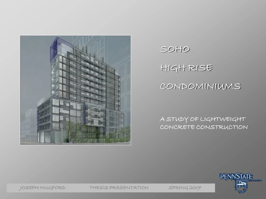
Explore the sleek architecture of high-rise condos in trendy SOHO, NY, featuring geometric shapes and transparent elements. Learn about the construction details and design elements in this captivating study.

E N D
SOHO HIGH RISE CONDOMINIUMS A STUDY OF LIGHTWEIGHT CONCRETE CONSTRUCTION
SOHO, NY,NY Trendy urban Neighborhood of Downtown Manhattan Simple geometric shapes create areas of transparency, light and shadow Sleek horizontal and vertical lines provide a rigid architectural grid for the building façade, a combination of colored and transparent glass Location and Architecture “This is a way to live at this time, in the poetry of the neighborhood. The emotion of architecture is linked to this harmony, to this relationship.” Jean Nouvel, Architect
Location and Architecture 15 Story Condominium Complex Height: 175’ Base: 70’ X 200’ Tower: 33’ X 170’ Sub-Cellar Parking Cellar Fitness and Spa 1st Floor Retail 10,000 SF 2-5: 27 Residential Units 11,800 SF/Floor 6-12: 13 Residential Units 4,650 SF/Floor 12-13: 2 Penthouse Units 6th Floor Roof Terrace Project Team Owner:WXIV/Broadway Grand Architect of Record:SLCE Architects Design Architect:AJN Ateliers Jean Nouvel Structural Engineers:Gilsanz.Murray.Steficek.LLP MEP Engineers:Cosentini Associates Curtain Wall Consultants:Gilsanz.Murray.Steficek.LLP Landscape Architect:Thomas Balsley Associates Lighting Consultant: Johnson Schwinghammer Inc. General Contractor:Pavarini Construction Co. Inc.
Existing Structure Floor Plans 10 ½” Flat Plate Uniform Steel #4 @12” o.c. bot. ea. way #5@16” o.c. top ea. Way Significant additional steel at column locations
Existing Structure Lateral System Base Thru 5th 6th Thru 13th
Structural Depth LWC FLAT PLATE DESIGN GOALS & STRATEGY Minimize usage of structural materials to offset the premium of LWC 1. Deflection equations derived by R.I. Gilbert 2. Add edge beams at building corners to support reduced slab 1. Elements that are more efficient in bending Offset reduced gravity loads 2. Uniform Cross section throughout height of building Consistent formwork Efficient load path with limited number of vertical discontinuities Reduce Slab Thickness Re-Design Shear Wall Core
Structural Depth Materials Existing System New System Floor Slabs 4 ksi NWC 4 ksi LWC Shear Walls 5 ksi NWC 5 ksi NWC
Structural Depth Flat Plate
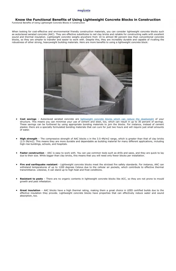
Structural Depth LWC VS. NWC • BENEFITS • Better acoustical performance • Better thermal properties • Higher fire resistance • Reduced autogeneous shrinkage • Improved contact zone between aggregate and concrete matrix • less micro-cracking as a result of better elastic compatibility • Higher blast resistance • Recycled additatives (fly ash, etc.) • SIGNIFICANT WEIGHT REDUCTION • -”Structural Lightweight Concrete” • Expanded Shale Clay and Slate Institute • COSTS • $20-30/ Cu. YD premium • compressive strengths exceeding 4 ksi not available • Alternative design and detailing to NWC
= K Support Factor 1 = K Shape Factor 2 = K Slab System Factor 3 D = Maximum Deflection a = r Effect of and n Structural Depth DEFLECTION RESEARCH AND APPLICATION • Gilbert-85 • Modification of Branson Beam Equation *sustained loading includes 50% live load 15√ρn 1.0 1.0 1.3 = 9” Slab Depth 2.0-1.2As’/As
Structural Depth DEFLECTION RESEARCH AND APPLICATION • Gilbert-99 • Modification of current ACI deflection equation • β accounts for tension cracking resulting from shrinkage and long term loading • Computed deflection multiplied by λ per ACI 318 (2.0 for long term loading) = l /390 0.4 (long term loading)
Structural Depth COLUMN TRANSFER Transfer Forces Moment=5434’k Shear=253k Shear Transfer Reinforcement 8-#7 @ Transfer walls 10-#7 @ Shear walls
Structural Depth LWC FLAT PLATE DESIGN
Structural Depth LWC FLAT PLATE DESIGN
Structural Depth LWC FLAT PLATE DESIGN Equivalent Frame Method Design Slab depth=9” Uniform Reinforcement #5@16” o.c. bottom ea. way #5@12” o.c. top ea. way Cantilever Beams 12X28 cantilever beams at building corners Corner columns increase to 20 x 32 @ Base Column Transfer Additional 8-#7 @Gravity Wall Additional 10-#7 @Shear Wall
Structural Depth Lateral System
Structural Depth SHEAR WALL DESIGN CRITERIA • Lateral forces • ASCE 7-05 Method 2 • ASCE 7-05 Equivalent Lateral Force Procedure (ELF) • Dynamic analysis (ETABS) • Deflection Total Building Drift H/500 (Wind) Total Building Drift H/400 (Seismic) Wind Earthquake Shear From Column Transfer
Structural Depth N-S Wind Controls
Structural Depth E-W Seismic Controls • Modal (Dynamic) Analysis • Response Spectrum • Base Shear=386 K (ELF) • R=4 (Normally Reinforced Shear Walls) T=2.06s IBC 2000 Function scaled to NYC SDS &SD1 Element Stiffness modified to account for cracking of concrete and force distribution Walls=0.7Ig (uncracked) Coupling Beams=0.35Ig
Structural Depth Story Displacements
Structural Depth Lateral System Modification Base Thru 5th 6th Thru 13th
LEED Breadth “A green building is one whose construction and lifetime of operation assure the healthiest possible environment while representing the most efficient and least disruptive use of land, water, energy and resources. The optimum design solution is one that effectively emulates all of the natural systems and conditions of the pre-developed site – after development is complete.” -Zeigler Design Goal • Gain LEED Certification of the SOHO High Rise (Implement 26/69 LEED Criteria): • Acknowledge criteria already met • Identify additional suitable criteria and associated costs
LEED Breadth Water Efficiency
LEED Breadth Associated Costs
Conclusions and Recommendations • Structural • 13-18% Reduction of Column Service Loads ~4500K • 8-10% Reduction in Slab Reinforcement • 19 ½” Total Height Reduction • 25% Reduction of Seismic Base Shear • Applicable to high seismic regions • Uniformity of shear wall system • Predictable lateral response • Consistent formwork • *Does not include possible column cross section reduction • Architectural • Elimination of shear wall section provides for architecturally free floor plan • Lower gravity loads may increase sellable floor area by reducing column cross sections
Conclusions and Recommendations LEED It should be the goal of developers and designers to implement design solutions that not only provide low first cost, but also improve the world and environments we live in. Implement additional LEED criteria that benefit occupants and meet allowable development budget Certification carries significant cost and schedule implications Notable social status symbol
AE Faculty GMS.LLP SLCE ARCHITECTS FAMILY & FRIENDS THANK YOU