Download
1 / 33
380 likes | 688 Vues
Modeling Unsteady Aerodynamics for Floating Offshore Wind Turbines. Evan Gaertner. Agenda. Unsteadiness aerodynamic environment for FOWTs Aerodynamic modeling techniques Modeling work at UMass Amherst. Floating Offshore Wind Turbines (FOWTs). Benefits: Access to strong wind resources

E N D
Modeling Unsteady Aerodynamics for Floating Offshore Wind Turbines Evan Gaertner
Agenda • Unsteadiness aerodynamic environment for FOWTs • Aerodynamic modeling techniques • Modeling work at UMass Amherst
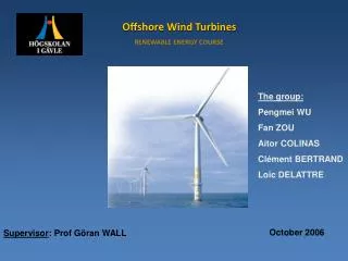
Floating Offshore Wind Turbines (FOWTs) • Benefits: • Access to strong wind resources • Proximity to population dense areas • Access to deep waters • Can be placed out of sight from shore • Little competition of use far from shore • Potential for simple installation • Only prototypes have been installed – technical challenges remain
Platform Motion • FOWTs subject to wave and wind loading • Mooring systems are not rigid • Leads to complex platform motion coupled to the wind and waves • 6 transitional and rotational DoF
Unsteady Aerodynamics • Wind turbine blades see highly unsteady flow
Platform Motion Time Series • How significant is the aerodynamic excitation from platform motion?
Reduced frequency • Unsteadiness is quantified using the reduced frequency (k) • Where ω is the angular frequency of an unsteady forcing term
Span-Wise Reduced frequency Demarcation frequency for the NREL 5MW
Spectral Analysis • Plots show the normalized, span-wise AoA PSDs • Excitation below the demarcation curve represents unsteady flow • Normalized platform DOFs are overlaid • Gives insight as to which are the largest sources of unsteady loading
Relative Aerodynamic Unsteadiness • Integrating the previous figures below the demarcation lines yields the total unsteady energy • Normalizing by the monopole shows relative increases in the aerodynamic unsteadiness for each platform Unsteady Energy Normalized by the Monopile
Agenda • Unsteadiness aerodynamic environment for FOWTs • Aerodynamic modeling techniques • Modeling work at UMass Amherst
Aerodynamic Modelling Techniques for FOWTs • Blade Element/Momentum (BEM) • Computational Fluid Dynamics (CFD) • Engineering Models • Dynamic Inflow • Vortex Methods
BEM Theory • Solves for rotor inflow using momentum balance across rotor disk annuli • Aerodynamic loading is determined using 2D blade elements • Predictions can be improved using a number of 3D and unsteady correction factors
BEM Continued Strengths • Relatively accurate load estimations • Computationally unintensive Limitations • Strictly 2D, 3D effects such as hub and tip losses are not rigorously accounted for • Can not model non-axial flow from yawed conditions • Uses static airfoil theory, neglects non-linear flow separation
CFD Models • Numerically solves for the Navier-Stokes equation at all points at each time step • Most rigorous approach for modelling interactions with turbulent 3D flow fields Limitations • Extremely computationally intensive • Has difficulty modelling both rotor wake convection and dynamic flow separation due to large differences in scale • Mostly used as a research tool rather than for design and load calculation work
Dynamic Inflow • Models the unsteady development of inflow over the rotor disk in response to unsteady changes such as pitch angle or thrust • Typically modifies BEM by introducing an inertial term • Lime lags are created using first order ODEs based on empirical time constants • Attractive for coupling with structural models Limitations • Uses a non-circulatory inertial term to approximate the circulatory lag in the wake development • Wake interaction is expected to be more severe due to platform motion so more rigorous treatment of the wake may be desirable offshore
Vortex Methods • Uses potential flow theory to model the blade as bound vortices • Vortices are shed from the blade to model the wake • Shed vortices are convected down stream and induces forces on the blade and all other points in the wake • Allows the wake to develop according to the flow conditions and interact with the blade inflow
Vortex Methods Strengths • Rigorous treatment of blade/wake interaction • Allows modelling of transient events like the blade yawing into the wake • Attractive for FOWTs because the platform motion can be explicitly included by superposition for calculating the vortex strength Limitations • Very computationally intensive (less than CFD however) • Can be sensitive to numeric error caused by initialization
Agenda • Unsteadiness aerodynamic environment for FOWTs • Aerodynamic modeling techniques • Modeling work at UMass Amherst
Wake Induced Dynamic Simulator (WInDS) • In-house free-vortex wake model developed at UMass Amherst • Developed to model rotor-scale unsteady aerodynamics including those caused by platform motion • Neglects blade section level, unsteady viscous effects • In inherent in potential flow models is an assumption of inviscid, incompressible, irrotational flow
Steady Blade Element Aerodynamics • Aerodynamic properties of airfoils determined experimentally in wind tunnels • Lift increases linearly with angle of attack (α) • At a critical angle, flow separates and lift drops • “Stall”
Dynamic Stall • Flow separation is a dynamic process in response to changes in α • “dynamic stall” • Causes: • Delayed detachment and reattachment • Increased maximum lift
Leishman-Beddoes (LB) Model • Commonly used, well documented method • Ex.: AeroDyn • Technique was developed to represent the physical stages of dynamic stall while minimizing • Experimental coefficients • Computationally intensity
LB Dynamic Stall Model • An implementation of the LB model was written in Matlab • The model was used to replicate unsteady pitch oscillation experiments from OSU
Preliminary Results Conclusions • Overall results are good for a parsimonious model • Significant improvement over quasi-steady data • Predictions improve at high reduced frequencies • Predictions are worst at high angles of attack, deep stall
Future Work: Coupling WInDS and the Dynamic Stall Model • Restructure the code to be called iteratively • Currently version is stand-alone based on a predetermined wind velocity input • Computational efficiency is an important concern • Modularize the LB model code • Simplify future research • Allow replacement sub-routines • Examined Relative WInDS and LB time steps for • Stability • Highest fidelity
Future Work: Analysis of the Coupled Code • Benchmark model outputs against 3-D experimental data • Several possible data sources: • Model Rotor Experiments In Controlled conditions (MEXICO project) • Full scale wind tunnel tests from NASA Ames • Wind tunnel tests from TU Delft • Examine the effects of FOWT platform motion on instances and severity of dynamic stall
Future for WInDS • Continue improving the computational efficiency • Rewriting the model in C++ following the FAST modularization framework • Write the dynamic stall model in C++ to be included in the FAST version
Thank You! Questions?
References Jonkman, J.M. 2007. “Dynamics Modeling and Loads Analysis of an Offshore Floating Wind Turbine.” NREL/TP-500-41958. Leishman, J.G. 2002. “Challenges in Modeling the Unsteady Aerodynamics of Wind Turbines.” AIAA Paper, 40th AIAA Aerospace Sciences Meeting, Reno, NV. Leishman, J.G. 2006. “Principles of Helicopter Aerodynamics.” Cambridge University Press: New York, NY. Sebastian, T. 2012. “The aerodynamics and near wake of an offshore floating horizontal axis wind turbine.” PhD Thesis presented to the University of Massachusetts, Amherst. Sebastion, T., Lackner, M.A. 2011. “Offshore floating wind turbines - an aerodynamic perspective.” In 49th AIAA Aerospace Sciences Meeting and Exhibit, Orlando, FL, 2011. American Institute of Aeronautics and Astronautics. Sebastion, T., Lackner, M.A. 2012. “Analysis of the Induction and Wake Evolution of an Offshore Floating Wind Turbine.” Energies, 5, pp. 968-1000. Sebastion, T., Lackner, M.A. 2012. “Characterization of the unsteady aerodynamics of offshore floating wind turbines.” Wind Energy, 16, no. 3, pp. 339-352.