Download
1 / 19
190 likes | 394 Vues
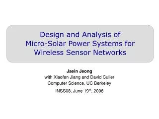
Design and Analysis of Micro-Solar Power Systems for Wireless Sensor Networks. Jaein Jeong with Xiaofan Jiang and David Culler Computer Science, UC Berkeley INSS08, June 19 th , 2008. Great Duck Island [SMP+04] . Golden Gate Bridge [Kim07]. Typical Wireless Sensornet Application.

E N D
Design and Analysis of Micro-Solar Power Systems for Wireless Sensor Networks Jaein Jeongwith Xiaofan Jiang and David CullerComputer Science, UC Berkeley INSS08, June 19th, 2008
Great Duck Island [SMP+04] Golden Gate Bridge [Kim07] Typical Wireless Sensornet Application • Typical sensornet application runs on battery. Limited Lifetime with Battery-Powered Node!
MPP Tracking SimpleDesign Multi-Level Storage [Everlast, 2006] [Prometheus, 2005] [Heliomote, 2005] [Ambimax, 2006] [Trio, 2006] [Fleck, 2006] Previous Works on Micro-Solar Power Systems • Solar-energy harvesting can be used as alternative to battery. • Several systems exist with a unique set of requirements. • But, they represent only particular points in the design space.Little analysis on performance in entire range of situations.
Heliomote [Raghunathan et al 05] Trio [Dutta et al 06] Contributions • Present a model for micro-solar power systems andDevelop a taxonomy of micro-solar design space. • Empirical analysis of two well-studied designs. • A design guideline for micro-solar systems.
Organization • System Architecture for Micro-Solar System • Design Considerations for Four Components. • External Environment • Solar Collector • Energy Storage • Load • Concrete Examples: Trio and Heliomote • Conclusion
System Architecture External Environment Sun Storage Monitoring (optional) Esolar_in Energy Storage Load Solar Collector EL1 ELn Esol = Econs Solar Panel Estorage_in Level-1 storage Level-n storage Mote Regulating Circuit Charging Controllerand Switch Software Charging Control (optional)
N Θ Vs Solar Panel Architecture –External Environment • Astronomical Model • Estimate solar radiation using angle Θ. • Solar panel output is given as Psol = cos Θ * Effpanel * A • Statistical Model • Refines the astronomical model by using weather variation statistics. • Effect of Obstructions
Architecture –Solar Collector • Converts solar energy to electricity. • Solar panel I-V curve describes possible operating point. • I-V curve moves depending on solar radiation. • Operating point dictated by output impedance.
Architecture –Energy Storage • Buffers energy and delivers in a predictable fashion. • Considerations: • System Requirements: Lifetime, capacity, current draw, size and weight. • Trade-offs between efficient energy transfer and charging logic. • Storage Elements • NiMH, Li+ for high energy density and supercap for long lifetime. • Configurations of energy storage : • Single element or multiple-level of storage elements
Architecture –Load • Mote is end consumer of energy in micro-solar system. • We abstract its behavior as load. • Radio, sensing and computation are main causes. • Duty-cycling is used to save energy consumption. • When the duty-cycle rate is R, average load is given as : Iestimate = R * Iactive + (1 – R) * Isleep
Comparative Study - Trio and Heliomote Trio Block Diagram Sun Storage Monitoring using uC ADC(CapV, BattV, Status) Esolar_in Energy Storage Load RU6730Solar Cell Esol = Switch Ecap Ebat Estorage_in Econs Telosrev.BMote Zener (SMAZ5V6) and Schottky (LLSD103A)Diodes Supercap(L1) Li+(L2) DC/DC Solar Collector Software Charging Control(Charging Switch, Thresholds) Heliomote Block Diagram Sun Esolar_in Energy Storage Load SolarWorld4-4.0-100Solar Cell HW Battery Monitor Econs Esol = Mica2Mote 2x AA NiMH DC/DC Ebat Estorage_in Diode HW Charge Controllerand Switch Solar Collector
Comparative Study(1) Solar-Collector Operation • Evaluate solar-collector matching by comparing Eop with Empp • Eop : daily solar radiation from the solar collector. • Empp : daily solar radiation that can be achieved with MPP. • Experiment (a) measures operating point (Iop, Vop) • Experiment (b) measures I-V curve at that moment.
Comparative Study(1) Solar-Collector Operation • Difference between Eop and EmaxP : • Trio: 4.8% of MPP, Heliomote: 22.0% of MPP • For Trio, SW charging allows setting Vop close to MPP after the measurement. • For Heliomote, Vop is set by battery voltage and protection circuit.This makes it hard to change Vop once the system is designed. Trio Heliomote
Comparative Study(1) Solar-Collector Operation • Useful range of the solar panel in a particular system is very narrow. • Power tracking circuits or algorithms are only meaningful within this small range.
Comparative Study(2) Energy Flow and Energy Efficiency • System efficiency for daily operation • Effsys = (Ebat + Ecap + Econs) / Esol • Daily cycle of a system: • Charge, Discharge, Saturation • Efficiency at different daily phase • Effbat−dis = Econs / Ebat−dis • Effcap−dis = Econs / Ecap−dis • Effchg = (Ebat−chg + Ecap−chg + Econs) / Esol Discharge(supercap) Discharge(battery) Discharge(battery) Charge
Comparative Study(2) Energy Flow and Energy Efficiency • System Energy Efficiency • Trio node : 19.5% to 33.4% • Heliomote : 6.9% to 14.6% • What makes this difference?
Comparative Study(2) Energy Flow and Energy Efficiency • Charging-discharging efficiency of Heliomote is as good as that of Trio, but its system efficiency is much smaller. • Much of solar energy is wasted during saturation phase. • Efficiency of Heliomote would be 31.9% to 41.9% without saturation.
Comparative Study(2) Energy Flow and Energy Efficiency • With Trio, supercap discharge period exists. • System runs on the supercap not on battery. • Effective battery lifetime increases by Tcap-dis / (Tbat-dis + Tcap-dis)
Conclusion • Presented a system model for micro-solar power system. • Analyzed two well-studied platforms, Trio and Heliomote. • Insights from the analysis: • Solar-collector: • Useful range of solar-panel voltage is narrow. • Can closely match operating point to MPPby setting operating point to this range without using MPPT. • Energy storage: • Multi-level storage improves system energy efficiency and lifetime.