Automotive Heating And Air Conditioning
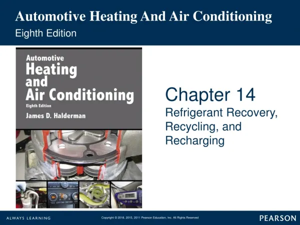
Automotive Heating And Air Conditioning. Eighth Edition. Chapter 14. Refrigerant Recovery, Recycling, and Recharging. Learning Objectives (1 of 3). 14.1 Prepare for the ASE Heating and Air Conditioning (A7) certification test content area “ A ” (A/C System Service, Diagnosis and Repair).

Automotive Heating And Air Conditioning
E N D
Presentation Transcript
Automotive Heating And Air Conditioning Eighth Edition Chapter 14 Refrigerant Recovery, Recycling, and Recharging
Learning Objectives (1 of 3) 14.1 Prepare for the ASE Heating and Air Conditioning (A7) certification test content area “A” (A/C System Service, Diagnosis and Repair). 14.2 Explain the steps involved in the service and repair of A/C systems. 14.3 Discuss the procedure for identifying refrigerants in an A/C system.
Learning Objectives (2 of 3) 14.4 Explain the procedure for refrigerant recovery in A/C systems. 14.5 Explain the procedure for recycling refrigerant in A/C systems. 14.6 Discuss the purpose of flushing an A/C system.
Learning Objectives (3 of 3) 14.7 Explain the procedure for evacuating an A/C system. 14.8 Discuss the procedure for recharging an A/C system. 14.9 Explain how to retrofit a R-12 system to a R-134a system. 14.10 Explain the purpose of sealants and stop leaks.
Clean Air Act • Section 609 • What are the requirements?
A/C Service Operations • Air conditioning service usually begins by identifying what refrigerant or other chemicals may be in the system and the recovery of whatever refrigerant is left in the system. • Recovery • Recycling • Connecting Gauges: what are the steps? • SAE RRR Machine Standards
FIGURE 14–1 A recovery unit removes refrigerant vapor from the vehicle. Then it filters the refrigerant before compressing it so it condenses and can be stored as a liquid in the storage tank.
Service and Repair of A/C Systems (1 of 2) • Identifying the refrigerant in a system using an identifier. • Recovery and disposal of contaminated refrigerant. • Evacuation of the system.
Service and Repair of A/C Systems (2 of 2) • Repair of the system as needed, including the replacement of system components. • Maintaining proper oil level when components are serviced. • Checking the oil level in a compressor or system.
FIGURE 14–3 A typical refrigerant identification machine. The readout indicates what kind of refrigerant is in the system. If a blend or some other contaminated refrigerant is discovered, it should be recovered and stored in a separate container to keep it from contaminating fresh refrigerant.
Refrigerant Identification (1 of 2) • STEP 1 The first step on all identifiers is CALIBRATION. • STEP 2 With the engine and the system shut off, connect the identifier to the low-side service port using the correct hose assembly for the system’s refrigerant type. • STEP 3 Check the filter on the identifier for the incoming gas.
Refrigerant Identification (2 of 2) • STEP 4 Allow a gas sample to enter the unit. • STEP 5 Read the display to determine the nature of the refrigerant. • STEP 6 When the analysis is complete, some units display instructions to disconnect the sampling hose and then bleed out the gas that was sampled.
FIGURE 14–4 A typical printout showing that the system has 100% R-1234yf refrigerant in the system.
Refrigerant Recovery (1 of 3) • STEP 1 Identify the refrigerant in the system. • STEP 2 Make sure the hoses have the proper shutoff valves and are compatible with the refrigerant in the system. • STEP 3 Connect the recovery unit to the system or to the center hose of the manifold gauge set, following the directions of the manufacturer.
Refrigerant Recovery (2 of 3) • STEP 4 Open the required valves and turn the machine on to start the recovery process, following the directions of the machine’s manufacturer. • STEP 5 Continue the recovery until the machine shuts off or the pressure reading has dropped into a vacuum.
Refrigerant Recovery (3 of 3) • STEP 6 Verify completion of recovery by shutting off all valves and watching the system pressure. If pressure rises above 0 PSI within 5 minutes, repeat steps 4 and 5 to recover the remaining refrigerant. • STEP 7 Drain, measure, and record the amount of oil removed from the system with the refrigerant and dispose of properly.
FIGURE 14–5 During the recovery process, oil from the system is separated into a container so the technician will know how much oil was removed.
Recycling Refrigerant • STEP 1 Open the valves or perform the programming steps required by the machine manufacturer and turn on the machine. • STEP 2 The machine operates until excess foreign particles and water have been removed or for a programmed length of time and then shuts off.
FIGURE 14–7 Recycling machines have a filter and desiccant that must be replaced after a certain amount of use.
Flushing an A/C System • Flushing is using a liquid or a gas to clean the inside passages of an air-conditioning system. • When a compressor fails, it usually sends solid compressor particles into the high and possibly the low sides, which can plug the condenser passages and orifice tube.
FIGURE 14–8 Portions of an A/C system can be flushed to remove debris and excess oil. Adapters are used to connect a flushing unit, which pumps the flushing material through the components. Most flushing machines are fully automated, meaning that it will vacuum, flush, recover, recycle, vacuum, and purge the cleaning solvent all automatically.
Replacing Components • General Guidelines • What are the following… • O-Rings • Tightening Connections • Service fittings and Caps • Schrader Valves
FIGURE 14–9 O-rings are usually made of neoprene rubber or highly saturated nitriles (HSN) to withstand high temperatures and flexing. O-rings should be changed during a retrofit procedure.
In-Line Filter • What is the purpose and function? • Installing an in-line filter • STEP 1 Recover the refrigerant from the system. • STEP 2 Select the location for the filter. The flexibility of hose allows a great deal of freedom. With metal tubing, locate a straight section of tubing slightly longer than the filter’s connections. • STEP 3 Evacuate and recharge the system after installation of the filter.
FIGURE 14–14 A typical aftermarket filter is installed in the suction line at the entrance to the compressor that is designed to catch any debris that could harm the compressor.
Refrigerant Oil • Adding oil • When it is determined that additional oil must be added, several types of low cost injectors can be used to push oil into a charged or empty system.
FIGURE 14–15 A variety of oil injectors are available for purchase. Some can be used while the system is under a vacuum, and some can force oil into a charged system.
Evacuating a System (1 of 3) • STEP 1 Connect the manifold service hoses to the system service ports if necessary but these are normally still connected from the recovery process. • STEP 2 Open both manifold valves completely (and the vacuum pump valve if there is one) and start the vacuum pump.
Evacuating a System (2 of 3) • STEP 3 Check the gauge pressures periodically. After about 5 minutes, the pressure should be lower than 20 inch Hg. • STEP 4 Continue evacuating until 500 microns is reached or for the desired length of time, close all valves, shut off the vacuum pump, and note the low-side pressure.
Evacuating a System (3 of 3) • STEP 5 After 5 minutes, recheck the low-side pressure. If the vacuum is held steady, the system is good and ready to be recharged. If the low-side pressure increases, a possible leak is indicated.
FIGURE 14–16 An air-conditioning vacuum gauge that reads in microns.
Recharging the System • The charge level is normally found on a specification decal fastened under the hood and includes the type and volume of refrigerant used. • The decal is attached to the compressor on some older systems. • If the decal is missing or illegible, charge specifications are also given in service information from the vehicle manufacturer or aftermarket A/C component suppliers.
FIGURE 14–19 The underhood decal states that this vehicle requires 1.81 pounds (0.822 Kg) of R-134a refrigerant.
Retrofitting R-134a into an R-12 System (1 of 5) • STEP 1 Visually inspect the system to ensure good condition. • STEP 2 Recover the R-12 from the system and remove as much oil-dissolved R-12 as possible. • STEP 3 Make any repairs to the system to cure problems that were found in step 1.
Retrofitting R-134a into an R-12 System (2 of 5) • STEP 4 If the compressor failed, remove the failed compressor, flush the system and/or install a high-side filter, and install the replacement compressor along with a new accumulator or receiver–drier. • STEP 5 Check the system to determine whether a high-pressure relief valve is used.
Retrofitting R-134a into an R-12 System (3 of 5) • STEP 6 If directed, replace the receiver–drier or accumulator. • STEP 7 Replace any line-fitting O-rings on connections that were disturbed, or as directed. • STEP 8 Replace any switches and valves as directed. • STEP 9 Add the proper type and amount of oil.
Retrofitting R-134a into an R-12 System (4 of 5) • STEP 10 Install the R-134a service fittings. • STEP 11 Fill out and install the identifying decal to properly identify the system. • STEP 12 Connect a vacuum pump to the system and pull a minimum vacuum of 29 inch Hg (500 microns) for at least 30 minutes to evacuate the system.
Retrofitting R-134a into an R-12 System (5 of 5) • STEP 13 Recharge the system using R-134a. • STEP 14 Operate the system and check for proper operation, paying careful attention to the high-side pressure. • STEP 15 Test for leaks.
FIGURE 14–21 When a system is retrofitted from R-12 (CFC-12) to R-134a (HFC-134a), the proper service fittings have to be used to help assure that cross-contamination does not occur.
Sealants and Stop Leaks • Sealants and stop leaks are designed to plug or stop small refrigerant leaks. • Most HVAC technicians dislike stop leaks as they are considered an inadequate or temporary repair method, and the best repair is to actually fix the leak.
FIGURE 14–23 Use A/C stop leak with caution. To help prevent sealant from getting into the RRR machine, use a sealant filter. For more information, visit http://www.airsept.com.
Summary (1 of 3) • The first refrigerant service operation is to identify the refrigerant in the system and check to make sure that it does not contain a sealant. • Evacuation is the process of removing the refrigerant form the system and storing it for reuse.
Summary (2 of 3) • Recharging is the process of charging the system with the specified amount of refrigerant. • Sealants should be detected before a system is evacuated to protect the recovery machine from damage and to prevent the sealant from being added to the refrigerant in the RRR machine.
Summary (3 of 3) • Retrofitting is the process of changing the refrigerant from one refrigerant to another, usually from R-12 to R-134a. • The refrigerant is recovered from a system so that service operations can be performed.