Download
1 / 52
570 likes | 975 Vues
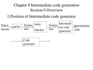
CHAPTER 8: GENERATION OF ELECTRICITY. Electrical energy for home and commercial use is produced by machines called generators. Generators convert mechanical energy to electrical energy. A generator consists of copper coils surrounded by magnets.

E N D
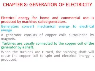
CHAPTER 8: GENERATION OF ELECTRICITY Electrical energy for home and commercial use is produced by machines called generators. Generators convert mechanical energy to electrical energy. A generator consists of copper coils surrounded by magnets. Turbines are usually connected to the copper coil of the generator by a shaft. When the turbines are turned, the spinning shaft will cause the copper coil to spin and electrical energy is produced.
Electricity is produced in generators • Generators require other sources of energy • Conversion of mechanical energy into electrical energy • Electromagnetic Induction • Turbine turns coils of wire in a magnetic field to produce a current
Thermal Generator - nr • There are various type of generator • Thermal generator • In a thermal power station, fossil fuels such as petroleum, coal and natural gas are used to heat water in a boiler to produce steam under high pressure.
Hydroelectric Generator - r • The steam is used to turn the turbines of a thermal generator. • In a hydroelectric power station, water flowing at high speed and pressure form the dam forces the turbines to rotate the generator to produce electrical energy.
Nuclear Generator -nr • In a nuclear power station, radioactive substances such as uranium and plutonium are used to produce heat by nuclear reactions in a reactor. The heat is used to heat water to produce steam. The steam is then used to turn the turbines of a nuclear generator.
Gas Turbine Generator - nr • In a gas turbine power station, natural gas or petroleum is burned in a high-pressure combustion chamber. The hot gases produced are used to turn the turbines of a gas turbine generator.
Diesel Generator -nr • In a diesel power station, a diesel motor is used to turn the copper coil of a diesel generator. Diesel generators are usually used to produce small supplies of electrical energy to small villages
Alternative Sources of Energy • Except for hydroelectric power stations, other types of power stations use non-renewable sources of energy. • 2. Two alternative sources of energy are: • i.Biomass • ii. Sun • 3. Biomass refers to the mass of living things in an area. The decomposition of the • remains and waste of living things by bacteria produces a gas called methane. Methane • can be used as a fuel. • There are two ways to tap solar energy to produce electrical energy. • Solar cells/solar panel convert energy from the sun into electrical energy.
Transformer • A transformer is a devices used for raising or lowering the voltage of alternating current. • A simple transformer consists of a soft iron core with two coils of wire on each side of the core as shown below. • There are two type of transformer; • A. the step-up transformer and • B. the step-down transformer. • A step-up transformer has more turns of wire on the secondary coil than the primary coil. • A step-down transformer has less turns of wire on the secondary coil than the primary coil as shown below. • The number of turns of wire in the primary and secondary coils determines the output voltage. • A step-up transformer has more turns of wire on the secondary coil and so produces a higher voltage in the secondary coil. • A step-down transformer has less turns of wire on the secondary coil and so produces a lower voltage in the secondary coil.
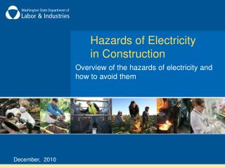
The Roles of Transformer in the Transmission and Distribution of Electrical Power. • The electrical energy produced at power stations needs to be transmitted and distributed to consumers. It is transmitted around the country in a network of cables called the power grid. • Some electrical energy is lost as heat during the transmission of electrical power. • Heat is generated due to the resistance of the electric cables. • The loss of electrical energy can be reduced by transmitting the electrical power at a high voltage. • This is achieved by using step-up transformers.
Components in the Electrical Power Transmission and Distribution System. • The components in the electrical power transmission and distribution system include: • National Grid Network • Transformer Stations • Switch Zones • Main Substation
The Functions of the Components in the Electrical Power Transmission and Distribution System. • Each component in the electrical power transmission and distribution system has its specific function. • The Transformer Station has transformers to step up or step down the voltage of electrical energy. • The Switch Zone allows the electrical energy to be transmitted through the National Grid Network. • The National Grid Network connects power stations at different places together and transmits electrical power to various places throughout the country. • Advantages • Electrical energy can generated according to the time needed. Some power station can be shut down at periods when energy need is low and reconnected when energy need increases, this can save costs. • If one of the power stations breaks down, its function can be taken over by another station in the network while waiting for the damaged station to be repaired. This avoids the cessation of electricity supply. Tryer 10 • The Main Substation has transformers that step down the voltage of electrical power to suitable value to be distributed to its branches.
Distribution • Construct & Maintain • 43,776 Switches • 670,496 Transformers • 1,448,794 Poles • 94,854 Circuit Miles • 317,820 Underground Structures • 1,300,000 Trees • 11,873 Cap Banks • 760,000 Street Lights • Plan Distribution Facilities • Reliability • Load Growth • Automation Transmission/Substation • Construct & Maintain • 16,945 Circuit Breakers • 4,459 Transformers • 13,585 Circuit Miles • 42,000 Relays • 15 UPS Sites • 4,000 Miles Communication Circuits • Operate • 904 Substations (16 manned) • 890 Transmission Circuits • 4,166 Distribution Circuits • Protect & Test • Automate • Plan Grid Facilities • Reliability • Load Growth • Interconnections • Administrative Contracts • Over 300 Grid Contracts
Transmission and Distribution of Electrical Power from the Stations to Consumers. • The electrical power produced at Power Stations in Malaysia has a voltage of 11 kV. It is then increased to 275 kV or 500 kV by step-up transformer stations. • The high-voltage electrical power is transmitted through overhead cables. • The electrical power then enters the Switch Zone and is transmitted through the National Grid Network to Main Substations at various places in the country. • At the Main Substations, the voltage of the electrical power is decreased to 33 kV by step-down transformers. • The electrical power is then channelled to factories involving heavy industries or other distribution Substation. • At the distribution Substations, the electrical power reduced further by step-down transformers to 11 kV for the use of light industries. • For the use of Towns/city or Houses, the electrical power is reduced to 240 V or 415 V either by the distribution substations.
Electrical Power Supply at Home • The mains voltage channelled to homes from the substation is 240 V. • Two types of electric currents, namely Direct Current (DC) & Alternating Current (AC). DC is current that flows only one direction (battery). • Electrical current (Alternating Current) is channelled to homes through cables. These cables consist of two types of wires, which are: • a. The Live wire - this type of wire carries current from the substation • to home. • b. The neutral wire - this type of wire returns current from homes to the • substation. Rumahkitabiasanya AC
Transmission – AC/DC • Alternating Current • Wire rotate past magnet causing a shift in direction • Happens many times each second • Cycles per second = Hertz Direct Current Electrons move in one direction
Transmission Lines • Distribution lines: • 33 kV down • Transmission lines: • 500 kv to 161 kV • Subtransmission lines: • 55 kV to 138 kV
The wiring system in homes includes the: • Fuse Box - Contains fuses that melt and break the flow of current to protect Electrical circuits from overloading or from short circuit. 2. Mains switch • Controls the electrical supply to all circuit in a home. 3. Circuit Breaker - A circuit is broken in specific situations for example when lightnings strike. 4. Live Wire – brown/BLACK • this type of wire carries electrical current to a home. 5. Neutral Wire - blue • this type of wire returns current to the substation. PMR2010 6. Earth Wire – green + yellow • this type of wire carries leaked current to the Earth. 7. Electric Meter - Measure the total amount of electrical energy used in a home.
Electrical Wiring System • Generally, the electrical wiring at our home is the single-phase wiring. • The three-phase wiring is usually used in places where the electrical energy consumption is higher. • The electrical wiring system at home consists of a fuse box, electric meter, main switch, circuit breaker, main electrical panel, live wire, neutral wire and earth wire.
Generally, the electrical wiring at our home is the single-phase wiring.The three-phase wiring is usually used in places where the electrical energy consumption is higher.
3-pin Plug PMR 2010 • The colour of the live wire is brown, the neutral wire is blue and the earth wire is yellow with green stripes.
Calculating the Amount of Current Flowing Through an Electrical Appliance. P V I
E (j) = P (kW) x T (h) = 45/1000 x 5 = 0.225 kWh = 0.225 kWh x RM0.20 = RM0.045 P E V I P T
THE FUNCTIONS OF FUSE AND EARTH WIRE. • A fuse is a device used to protect an electric circuit against excessive current. • It consists of a wire that will melt at a certain temperature. • The wire is usually made of an alloy of tin and lead. • There are two main types of fuses. • In a replaceable wire fuse, a length of wire is attached to the terminals • The cartridge fuse, consists of a wire enclosed in a cylindrical tube made of an insulating material as shown below. • The rating of a fuse is the maximum amount of current that can flow through the fuse without the wire of the fuse melting. • The rating of a fuse is always indicated on the fuse. • Common fuse ratings are 1 A, 2 A, 3 A, 5 A, 10 A and 15 A.
The Function of FusesPMR 2010 • When a short circuit occurs, there is low resistance and a large amount of current flowing in the circuit. • This may cause a fire and damage to electrical appliance. To prevent this, fuses are used. • During a short circuit will cause the wire of the fuse to heat up and melt. The circuit then becomes incomplete and current stops flowing in the circuit.
Determining the Suitable Rating of a Fuse for an Electrical Appliance. • The rating of a fuse is the value of the maximum current that is allowed to flow through the fuse without causing the wire of the fuse to melt. • Fuses to be used in electrical appliances should have a rating of just slightly more than the current which the electrical appliances will use under normal working condition. • For example, a fuse of 3 A may be used for an electrical appliance that operates on a current of 2.5 A.